<--Back
Contents
Project around the ATMEGA 1284P and 328P. 1
Project around the
ATMEGA 1284P. 3
The ATMEGA 328P and
1284P processor. 4
Needs for the project. 6
Install the libraries
in the Arduino IDE. 7
The PCB. 8
Burning a bootloader
on the 1284P. 8
Use a FTDI to program
the chip. 11
Turning on and off
LED’s. 13
Measuring the Crystal
frequency. 14
Turn a 5V PWM signal
to a 12V PWM signal 15
Lower a 5V signal to
a 3.3 V signal 15
Lower 7V – 15V to 5 V.. 16
Use the DCF77 time
receiver. 17
Using a FM-radio to
receive time from the RDS signal and tune to a station. 23
Using a GPS to
receive time and position on the globe. 29
Use the Bluetooth
HC-05 and HM-10 4.0 BT-BLE modules to send and receive messages. 29
Change the name of a
HM10 BLE with an FTDI 34
Communicate with
Android, Windows and Apple devices. 35
Communicate with a
LCD display. 35
Communicate with a
128 by 64 pixel 12864 OLED display. 37
Display on a 8 Digit
LED Display MAX7219 7 Segment Digital Tube. 37
Add a temperature
sensor Dallas DS1820. 39
The WS2812
and SK6812 colour
LEDS
. 42
Use the 32 bytes NVRAM in
the DS3231 time module
Use buttons. 42
Use a rotary. 43
Adjust some 1284P
features. 43
Some knowhow of the
1284P. 43
Projects around the ATMEGA 328 and 1284P
For people born
in the 50-ties of the previous century the Arduino brings back hobbies from
their youth.
When I was around 20 the first calculators became affordable. Later the
Commodore 64, Acorn BBC B computer and then MS-DOS on IBM-compatible PC were
the standard. I learned programming in Lattice C and couple device to the PC. For
the single programmer like me C-programming ended when C++ compilers were
designed to work with projects. Borland C V4 was for me the last and almost
perfect IDE. After W95 and the connection to internet computers became more
secure. Now with Windows 10 and IPad’s, the systems were consumable and closed
devices. You need assistance from external companies to connect their closed
devices to your computer system and dozens of people to open network ports,
allow access to the completed closed PC.
The Arduino and
Raspberry computers are therefore not surprisingly extremely interesting for
people just in or on the brink of their retirement and a lot of time to spent
and learn again.
I chose the
Arduino and used the Word clock as a project to start to learn simple
electronics and use my programming skills to hobby again.
The Arduino
offers a simple IDE (integrated development environment) and C
(C++) as programming
language. Raspberry’s and similars are using
UNIX to operate and is far too powerful
for the smaller projects.
The ATMEGA1284P
processor from ATMEL has more program memory than the ATMEGA328; 128K instead
of 32K memory. Especially when several libraries are used in the project, WS2812
RGB and SK6812 RGBW LEDs are added, 32K of memory becomes tight. For these
purposes Arduino developed the Arduino Mega around the ATMEGA2560 chip. But
for the amateur electronic this is troublesome because this is a SMD chip and
difficult to solder.
The ATMEGA1284P is a large 40 pin chip that can be easily
incorporated in a self-made PCB.
I
planned to built a four-language clock. It uses 625 SK6812 LEDs and I needed
more memory than the 328 chip provided.. (Time overhauled me with the
alternative Arduino Nano Every with 48K memory.)
During the
'evolution' of
the software and hardware around a Word clock several input and output
possibilities were required. That is a clock module, bit shift registers to
control LEDS or relays at a higher voltage level than 5V, Bluetooth connection,
DCF77, FM-radio and GPS receivers to adjust the time to atomic time clock
transmitters.
Burning the chip on the PCB with a FTDI connection to a PC,
working at voltage levels of 3.3V, 5V and 12V and pulse width modulation to
adjust the LED intensity. Also working with RGB WS2812
and SK6812 LEDs was one of the
needs.
I realized that
the designed board became a universal board with large and easy to solder DIP ATMEGA
328 or ATMEGA 1284P processor as the base.
Several source
codes are located here and here on
Github
By using
#define’s attached modules and their coding can be turned on or off. The
program is tested and can be used with ATMEGA328 chip, an Arduino UNO, Arduino Nano
or an ATMEGA1284P.
Programming with the 1284P has some quirks that had to be written
down and here is the page ‘How to Do’ this.
The page also offers an
overview of the parts I use, their characteristics and how to operate them.
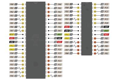
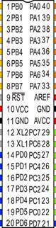
The ATMEGA 328P and 1284P processor
ATMEL produces
many processors with many possibilities. The ATMEGA 328P processor is used in
the Arduino Uno and very popular. 328 stand for 32 KB memory 8 bits addressing.
The 1284P has 128K memory and also 8 bits addressing. The P stands for
PicoPower. In this article we use the P versions of the chip. The –PU stands
for PDIP package that are the dual-line 28 (328) or 40 pin (1284) chips.
So, when
looking for the processors; buy the 328P-PU or 1284P-PU chips.
Beside the
memory size of the chip there are also differences in the amount of pins on the
chip, 28 versus 40 and therefore also the number of analogue and digital ports.
The other
characteristics of the processors are comparable. Both processors operate at
voltages between 1.8V and 5.5V. The low voltage of 1.8V can be used when
oscillators between 0 and 4 MHz are used. The chip contains an internal
oscillator that runs at 8 MHz. We will use an external oscillator of 16 MHz.
This should be used after burning the bootloader in the chip. The bootloader
supplied with the Arduino IDE’s for this chip runs at 16 MHz and needs a
working voltage between 4.5V and 5.5V to run at this speed. One can use these
chips for low power consumption projects because the chip also has many sleep
modes possibilities.
Features of
the ATMEGA processors noted on their datasheets
|
1284P
|
328P
|
|
•
High-performance, Low-power AVR® 8-bit Microcontroller
• Advanced
RISC Architecture
– 131
Powerful Instructions – Most Single-clock Cycle Execution
– 32 x 8
General Purpose Working Registers
– Fully
Static Operation
– Up to 20
MIPS Throughput at 20 MHz
– On-chip
2-cycle Multiplier
• Nonvolatile
Program and Data Memories
– 128K Bytes
of In-System Self-Programmable Flash
Endurance:
10,000 Write/Erase Cycles
– Optional
Boot Code Section with Independent Lock Bits
In-System
Programming by On-chip Boot Program
True
Read-While-Write Operation
– 4K Bytes
EEPROM
Endurance:
100,000 Write/Erase Cycles
– 16K Bytes
Internal SRAM
– Programming
Lock for Software Security
• JTAG (IEEE
std. 1149.1 Compliant) Interface
–
Boundary-scan Capabilities According to the JTAG Standard
– Extensive
On-chip Debug Support
– Programming
of Flash, EEPROM, Fuses, and Lock Bits through the JTAG Interface
• Peripheral
Features
– Two 8-bit
Timer/Counters with Separate Prescalers and Compare Modes
– Two 16-bit Timer/Counter
with Separate Prescaler, Compare Mode, and Capture
Mode
– Real Time
Counter with Separate Oscillator
– Six PWM
Channels
– 8-channel,
10-bit ADC
Differential
mode with selectable gain at 1x, 10x or 200x
–
Byte-oriented Two-wire Serial Interface
– Two
Programmable Serial USART
–
Master/Slave SPI Serial Interface
–
Programmable Watchdog Timer with Separate On-chip Oscillator
– On-chip
Analog Comparator
– Interrupt
and Wake-up on Pin Change
• Special
Microcontroller Features
– Power-on
Reset and Programmable Brown-out Detection
– Internal
Calibrated RC Oscillator
– External
and Internal Interrupt Sources
– Six Sleep
Modes: Idle, ADC Noise Reduction, Power-save, Power-down, Standby
and Extended
Standby
• I/O and
Packages
– 32
Programmable I/O Lines
– 40-pin
PDIP, 44-lead TQFP, and 44-pad QFN/MLF
• Operating
Voltages
– 1.8 - 5.5V
for ATmega1284P
• Speed
Grades
– 0 - 4 MHz @
1.8 - 5.5V
– 0 - 10 MHz
@ 2.7 - 5.5V
– 0 - 20 MHz
@ 4.5 - 5.5V
• Power
Consumption at 1 MHz, 1.8V, 25°C
– Active: 0.4 mA
– Power-down
Mode: 0.1 μA
– Power-save
Mode: 0.7 μA (Including 32 kHz RTC)
|
•
High-performance, Low-power AVR® 8-bit Microcontroller
• Advanced
RISC Architecture
̶ 131
Powerful Instructions – Most Single Clock Cycle Execution
̶ 32 x 8
General Purpose Working Registers
̶ Fully
Static Operation
̶ Up to
20 MIPS Throughput at 20MHz
̶
On-chip 2-cycle Multiplier
•High
Endurance Non-volatile Memory Segments
̶
32KBytes of In-System Self-Programmable Flash program memory
̶ 1KBytes
EEPROM
̶
2KBytes Internal SRAM
Write/Erase
Cycles: 10,000 Flash/100,000 EEPROM
̶- Data
retention: 20 years at 85C/100 years at 25C(1)
̶
Optional Boot Code Section with Independent Lock Bits
̶ In-System
Programming by On-chip Boot Program
̶True
Read-While-Write Operation
̶
Programming Lock for Software Security
-Atmel®
QTouch® library support
̶
Capacitive touch buttons, sliders and wheels
̶ QTouch
and QMatrix® acquisition
̶ Up to
64 sense channels
• Peripheral
Features
̶ Two
8-bit Timer/Counters with Separate Prescaler and Compare Mode
̶ One
16-bit Timer/Counter with Separate Prescaler, Compare Mode, and
Capture Mode
̶ Real
Time Counter with Separate Oscillator
̶ Six
PWM Channels
̶
8-channel 10-bit ADC in TQFP and QFN/MLF package
- Temperature
Measurement
̶
6-channel 10-bit ADC in PDIP Package
̶
Temperature Measurement
̶
Programmable Serial USART
̶
Master/Slave SPI Serial Interface
̶
Byte-oriented 2-wire Serial Interface (Philips I2C compatible)
̶
Programmable Watchdog Timer with Separate On-chip Oscillator
̶
On-chip Analog Comparator
̶
Interrupt and Wake-up on Pin Change
̶
Power-on Reset and Programmable Brown-out Detection
̶
Internal Calibrated Oscillator
̶
External and Internal Interrupt Sources
̶ Six
Sleep Modes: Idle, ADC Noise Reduction, Power-save, Power-down, Standby, and
Extended Standby
• I/O and
Packages
̶ 23 Programmable
I/O Lines
̶ 28-pin
PDIP, 32-lead TQFP, 28-pad QFN/MLF and 32-pad QFN/MLF
• Operating
Voltage:
̶ 1.8 -
5.5V
Temperature
Range:̶ -40C to 85C
• Speed
Grade:
̶ 0 -
4MHz@1.8 - 5.5V,
0 -
10MHz@2.7 - 5.5.V,
0 - 20MHz @
4.5 - 5.5V
• Power Consumption
at 1MHz, 1.8V, 25C
̶ Active
Mode: 0.2mA
̶
Power-down Mode: 0.1μA
̶
Power-save Mode: 0.75μA (Including 32kHz RTC)
|
|
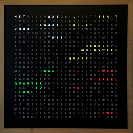
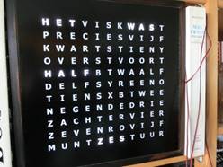
As written
before the project is built around a word clock. This clock drives 23 LEDs
strips to make up the words that light up in matrix of letters to tell the
time. Like: It was “five past three”
Here the text
displays the words in Dutch:
“Het was half zes”. That translates to: It was half
past five.
This clock
uses Shift registers combined with a Darlington transistor array ICs to
switch from 5V to 12V to turn on or off LED strips voltage,
|
|
|
Bluetooth
connection to set time and turn on- off features, a DS3231 clock module with
I2C connection, FTDI connection to program the chip, rotary or button
control, RDS time receiver from an RDA5807 FM-radio module and a LCD or OLED
display connection, a 8 digit LED display and a Dallas temperature sensor.
To make the word
clock with RGB colour LEDs instead of white LED strips, WS2812 RGB LED’s were
used.
All together
a project that uses many techniques and a lot of research.
The project
is built around the standard ATMEGA 328 chip with 32K memory or the 1284
processor chip with 128K memory.
|
The programming
environment from Arduino: Download
IDE 1.8.13 of
higher from: https://www.arduino.cc/en/Main/Software
Libraries:
Download or install
------------------------------------------------------
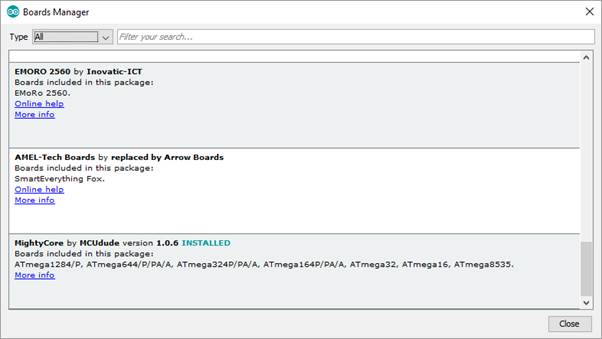
https://github.com/mcudude/MightyCore Library for the 1284P board
Boards
Manager Installation
This
installation method requires Arduino IDE version 1.6.4 or greater.
•Open the
Arduino IDE.
•Open the File
> Preferences menu item.
•Enter the
following URL in Additional Boards Manager URLs: https://mcudude.github.io/MightyCore/package_MCUdude_MightyCore_index.json
◦Separate the URLs using a comma ( , ) if you have more than one URL
•Open the Tools
> Board > Boards Manager... menu item.
•Wait for the
platform indexes to finish downloading.
•Scroll down
until you see the MightyCore entry and click on it.
•Click Install.
•After
installation is complete close the Boards Manager window.
------------------------------------------------------
https://github.com/fdebrabander/Arduino-LiquidCrystal-I2C-library LiquidCrystal_I2C
All other used
libraries are Arduino standard libraries.
If everything
is installed from the Arduino IDE (Open from the IDE menu: Sketchà Include library à
Manage
libraries) you will see the following directories in your library folder. The
library folder is stored between you script folders in the Arduino folder in
your Documents folder:
<DIR>
Encoder
<DIR>
LedControl
<DIR>
MAX31850_DallasTemp
<DIR>
NewliquidCrystal
<DIR>
OneWire
<DIR>
RTClib
<DIR>
Time
<DIR>
TM1638
The includes:
#include
<Wire.h>
#include <LiquidCrystal_I2C.h>
#include
<RTClib.h>
#include <EEPROM.h>
#include
<SoftwareSerial.h>
#include
<Encoder.h>
#include
"DCF77.h"
#include
"TimeLib.h"
#include
<LedControl.h>
#include
<DallasTemperature.h>
The 1284P PCB
(printed circuit board) is not essential. (Send me a mail
if you want a spare one)
You can wire and solder the project up yourself. The project will be split in
project parts and every part can work on itself with the ATMEGA1284P or 328P
processor chip.
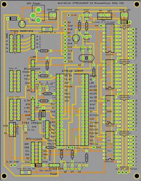
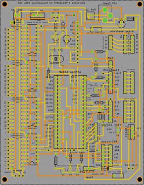
I use Fritzing
to design my PCB. Download the Fritzing design program here: http://fritzing.org/download/
The Fritzing
file of this PCB can be found here:
https://ednieuw.home.xs4all.nl/Woordklok/ATMEGA1280P_Project/Woordklok1284PV10.zip
Woordklok1284PV21.fzz
When processor
chips are bought they are often without bootloader and then this must be
installed on it.
The bootloader
is a small program and during burning the bootloader also different settings
(fuses) are set for the chip. Something like the bios in PC’s but then as a
program.
After power up or a reset of the processor the bootloader starts and
listen to the RX and TX pins for a short time.
In that time a program can be uploaded
in the processor and started. It is possible to burn a program directly in the
chip without a bootloader to spare approximately 1K of memory.
For me that is
too much fuss. As can be seen later using the bootloader makes life easier and
the chip easy to reprogram.
For fuses and
lock bits see: http://www.engbedded.com/fusecalc
There are 8
bits in the low fuse byte. These 8 bits are explained here:
•Bit-7: CKDIV8:
When set divides the clock speed by 8
•Bit-6: CKOUT:
When set clock pulses are output on PB0 (Pin 14)
•Bit-5: SUT1:
Startup time delay
•Bit-4: SUT0:
Startup time delay
•Bit-3: CKSEL3:
Set the clock source
•Bit-2: CKSEL2:
Set the clock source
•Bit-1: CKSEL1:
Set the clock source
•Bit-0: CKSEL0:
Set the clock source
There are 8
bits in the high byte fuse also. These are:
•Bit-7:
RSTDISBL: External Reset disable
•Bit-6: DWEN:
Debug Wire enable
•Bit-5: SPIEN:
Enable serial programming and data downloading
•Bit-4: WDTON:
Watchdog timer always on
•Bit-3: EESAVE:
Preserve EEPROM memory through chip erase
•Bit-2:
BOOTSZ1: Sets the bootloader memory size
•Bit-1:
BOOTSZ0: Sets the bootloader momory size
•Bit-0:
BOOTRST: Select the reset vector
Download: https://github.com/mcudude/MightyCore
This
installation method requires Arduino IDE version 1.8 or higher.
Open the Arduino
IDE.
Open the File
> Preferences menu item.
Enter the
following URL in Additional Boards Manager URLs: https://mcudude.github.io/MightyCore/package_MCUdude_MightyCore_index.json
Open the Tools
> Board > Boards Manager... menu item.
Wait for the
platform indexes to finish downloading.
Scroll down until
you see the MightyCore entry and click on it.
Click Install.
After installation
is complete close the Boards Manager window.
Open in Tools of
the IDE à Board à board manager
Install
MightyCore by MCUdude
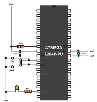
Parts:
Resistors 10kΩ,
330Ω 1/4W
Crystal 16 MHz
Two ceramics 22 pF
capacitors
Two 0.1 µF
electrolytic capacitors
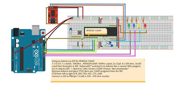
Connect the
part as shown above.
Connect a LED between
a 330 ohm resistor and pin PD5 (D13) of the 1284P processor and connect the
other pin to ground. This will blink the LED13 in the Blink program
Connect a LED
between a 330 ohm resistor and pin 9 of the Arduino for the ‘heartbeat’ and
connect the other pin to ground.
Connect Arduino
pin 10 to Reset.
Connect Arduino
pin 11 to PB5.
Connect Arduino
pin 12 to PB6.
Connect Arduino
pin 13 to PB7.
Connect VCC and
GND of the Arduino to the power supply on the breadboard.
1.
Load the program
ArduinoISP from the examples in the IDE in an Arduino Uno with board settings:
Aduino UNO.
2.
Change board setting in
the IDE to ATMEGA 1284 and
3.
Choose 1284p as variant
and B.O.D. = 2.7V, Pinout: standard, Clock: 16 MHZ external
4.
Programmer: “Arduino as
ISP”
5.
Burn the bootloader to
the ATMEGA1284p (in menu Tools -> burn bootloader).
6.
Write a ‘B’ on the chip
so you know the chip had a bootloader in it.
Use a FTDI to
program the chip
|
To upload a
program in to the ATMEGA a FTDI FT232RL USB to serial breakout board is used.
This piece of hardware takes care of the communication between the USB port
of the PC and the serial port on the ATMEGA chip. Before a program can start
to upload the bootloader in the processor chip is activated by pulling down
the Reset on the chip for a short period. This is done by the DTR-signal from
the FTDI board. A 0.1 µF capacitor between DTR and RST makes a nice signal
drop on the reset pin.
Pull the
reset wire from the Arduino UNO pin 10 and connect the other 0.1uF capacitor
pin of the FTDI DTR.
DTR <->
0.1uF <-> Pin 9 RST ATMEGA1284P
Remove the
VCC and GND wires from the Arduino.
|
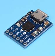
CP2102 MICRO
USB to UART TTL Module
|
|
Place the
FTDI in the breadboard with the ATMEGA1284P
Connect the
DTR to the 0.1uF capacitor. Connect other pin of the the 0.1uF capacitor to
Reset pin9 of the ATMEGA1284P. Connect a 10k resistor between Reset pin9 and
5V
Connect from
the FTDI module: Rx to PD1, Tx to PD0, VCC to VCC, Do not connect CTS and GND
to GND.
Now you can
upload a program from the IDE to the ATMEGA1284P.
|
On the board
several pins are connected to a LED. It is, of course possible to use these connections
for other controls and leave the resistor and LED out the board. Pins 7, 14 and
15 can be used for a PWM-signal. Pins 5, 10 and 19 are digital pins. In the
program below all pins are written to as analogue pins with values between 0
and 255. Pin 15 was not flagged as a PWM pin in the schematic shown above but
it behaves as a PWM pin because the LED faints like a heartbeat like pin 7 and
14.
|
ATMEGA1284-heartbeat5_PWM.ino
// Modified heartbeat for ATMEGA1284P
// Ed Nieuwenhuys Oct-2016
#define PWM_03 3 // PWM pin
#define LED_05 5 // digital pin
#define LED_07 7 // PWM pin
#define LED_10 10 // digital pin
#define LED_14 14 // PWM pin
#define LED_15 15 // PWM pin
#define LED_19 19 // digital pin
uint8_t
hbval = 128;
int8_t
hbdelta = 8;
void setup()
{
pinMode(PWM_03, OUTPUT); // initialize pins as output.
pinMode(LED_05, OUTPUT);
pinMode(LED_07, OUTPUT);
pinMode(LED_10, OUTPUT);
pinMode(LED_14, OUTPUT);
pinMode(LED_15, OUTPUT);
pinMode(LED_19, OUTPUT);
Serial.begin(9600); // setup the serial port to 9600
baud
Serial.println("Heartbeat started");
}
// the loop function runs over and over again forever
void loop()
{
heartbeat();
}
void heartbeat()
{
static unsigned long last_time = 0;
unsigned long now = millis();
if ((now - last_time) < 40) return;
last_time = now;
if (hbval > 230 || hbval < 20 ) hbdelta = -hbdelta;
hbval += hbdelta;
analogWrite(LED_05, hbval);
analogWrite(LED_07, hbval);
analogWrite(LED_10, hbval);
analogWrite(LED_14, hbval/16);
analogWrite(LED_15, 235-hbval);
analogWrite(LED_19, 255-hbval);
analogWrite(PWM_03, hbval);
}
|
|
|
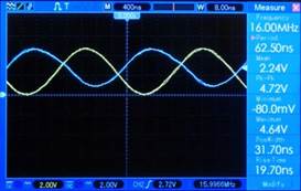
What seemed
difficult was measuring the frequency of the crystal with an oscilloscope.
Just connecting the two pins to the scope was of course not working. The crystal
is a piezo element and some force had to be applied to it. There are
obviously two crystals in the casing and if one applies a force, in this case
5V blocked with a 22pF capacitor to earth, onto the crystal it starts
resonating. Just place the pin of the oscilloscope to one of the Xtal pins
when the system is powered and a smooth sinus wave is displayed on the scope.
The two signals are complementary.
|
|
Several ports
on the ATMEGA 1284P processor can generate a Pulse Width Modulation (PWM)
signal. PWM signals can be used for many purposes like dimming LED intensity or
let motors spin around.
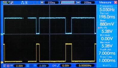
The signal
alternates between 0 and 5V and the time a 5V signal is given is called the
duty cycle. With a duty cycle of 50% half of the time the voltage is 5V and the
other half 0V. The frequency used for the signal is 500 or 1000 Hz depending on
the pin number.
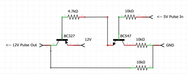
When you have
to drive 12V LED’s the 5V pulse must be amplified. This is done with two
transistors.
The BC547 NPN transistor
and the PNP BC327 transistor.
This transistor
circuit can supply a continuous power of 0.8A.
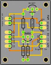
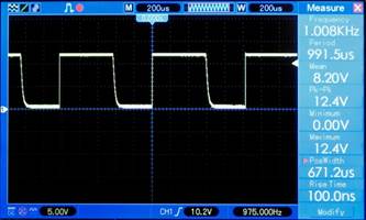
The output
signal is almost a perfect block.
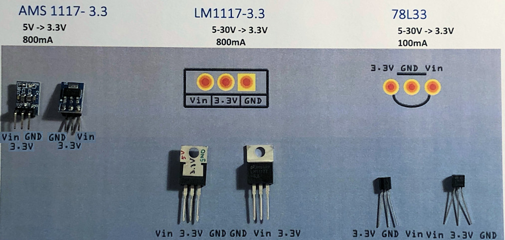
Depending
on its use below are some options are shown.
They all dissipate heat to lower
the voltage and a step down converter
is more efficient.
When the PCB in
this project is used 5V and 12V is needed; 5V for the electronics and 12V for
the LEDs.
Very handy is a
12V/5V power supply. Search for: AC-DC Dual Output 220V to 12V 5V Isolated
Switch Power Module Buck.
But if one does
not want to have 220V in the project or want to use an external power supply
one need to lower the voltage
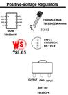
Four types of
voltage regulator are shown. The Step down converters are the most efficient.
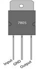
The L7805CV
often needs to be cooled with a heat sink. This is a piece of metal to which
the power regulator is attached.
The 78L05 is
for small currents up to 0.1 A. (TO-92 and TO-220 is the name of the casing,
how the regulator looks)
|

|
|
|
|
|
|
|
78L05 TO-92
100 mA of
output current.
|
L7805CV
TO-220
1.5A of
output current
|
DC-DC
9V/12V/24V to 5V 1.5A Step Down Power Module
|
Mini-360
DC-DC 4.75V-23V to 1V-17V Buck Converter Step Down
|
It is always
trouble to get a time signal in your program. Nowadays time modules are very
cheap and exact and deviate no more than 10 seconds every year. But that
annoying summer and winter time changing two times a year in troublesome.
You can pick time
from a time server from internet but then you need WIFI or cable connection to
your router. You can use a GPS to retrieve the time from but then you have to
located your receiver to a location it ca see the sky. You can use FM-radio and
extract the RDS time signal. But radio stations are not exact with their time
and may deviate minutes from the real time. Also FM-radio stations do not have
a fixed frequency for every station.
You can use an old telephone and a cheap SIM.
But we can also
fall back to an ancient signal stored in a radio wave.
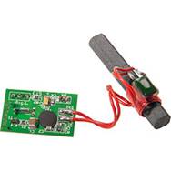
Since 1905 time
signals are transmitted by radio. This signal can be received with low cost
receivers made of a ferrite rod. In Europe the DCF77 signal sent from a
transmitter situated in Mainflingen, Germany at a frequency of 77.5 kHz.
|
|
|
|
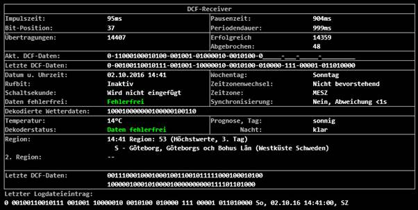
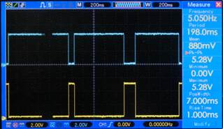
Time pulse signal
|
DCF77
receiver module
|
The time signal
is just like a Morse-signal, but a slow one. In every second there is a short
or long pulse. The short pulse is 0.1 s and the long lasts 0.2 s. After 59
seconds one has a sequence of 59 bits. The last second is silent. This is the
alignment signal.
A lot of
information is stored in these 59 bits.
This signal can
be fed into the ATMEGA processor. But there is also a drawback. Microwaves,
processor chips and other radio wave interfere with this perfect pulse. The
ferrite rod has to be placed horizontal and preferable pointing perpendicular to
the transmitter.
Several
libraries are already written to translate the signal to a time stamp. The
Arduino IDE contains the library from Thijs Elenbaas and this library can be
installed from the library manager.
I wrote a non interrupt
routine to decode the signal. Combining both methods can boost the proper
received times by more than 50%.
Have a look at the DCF77-transceiver
clock or here on Github
https://github.com/ednieuw/DCF77_NoInterrupt
and here for the library:
https://github.com/ednieuw/EdSoft_DCF77
For our project
a LED is used to check if a proper signal is received. The LED should blink
regularly every second. If you look closed you can see the difference between a
long and a short pulse. If the led flashed erratically then you should turn the
rod or move it away from your PC.
WS2812 RGB LEDs
have a small processor in every LED and this processor interferes with the
reception.
I bought my DCF77-module
from ELV elektronik AG. The DCF-2 module operates between 1.2 V – 15 V and gives a pulse
between 0 and 5 V and therefore easy to connect in the Arduino environment.
Some
DCF-modules give a 5 V signal on the pulse while others have an inverted
signal.
There are two
ways to deal with it.
Invert the
signal with a NPN transistor like the BC327.
|
|

|
|
DCF77 time
signal
|
Pulse inverter
|
Or use the not
documented library function to invert the signal.
The library
initialization contains a third parameter. OnRisingFlank. This is default set
to true (HIGH).
Initialize the
library as follows: DCF77 DCF = DCF77(DCF_PIN,DCF_INTERRUPT, LOW);
Below are some
not documented functions the library gives you to use:
DCF77(DCF77Pin,
DCFinterrupt, OnRisingFlank); // Initialize library
time_t
getTime(); // Returns the
current time in CET
time_t getUTCTime();
// Returns the current time in UTC
Start();
//
Start listening to DCF77 signal
Stop(); //
Stop listening to DCF77 signal
After updating
the libraries and boards some compiling errors occurred:
After changing
#include "Time.h” in #include "TimeLib.h" the source code
compiled again without errors.
Informational
links with info about DCF receivers:
Online signal from Mainflingen on website
Explains
the bits in the received string Arduino projects 4you
HKW-Elektronik
GmbH Sells all kinds of
receivers
Rheinturmfunkuhr mit Arduino
Arduino DCF77 radio clock receiver, Matthias Dalheimer
Github Thijs Elenbaas
Conrad receiver
http://www.elv.de/dcf-empfangsmodul-dcf-2.html
The program
below can be used with an ATMEGA 1284P or the Arduino UNO 328P processor. Four
libraries are needed and all are included in the Arduino IDE.
Connect the
DCF-77 and the RTC-clock. The clock can be the Tiny RTC-module or the DS3231 RTC-
module than can be bought cheap on EBay. But probably every I2C clock module
will work.
The LED should
be flashing regularly, every second once. Keep de DCF77 antenna far away from your
PC. An oscilloscope is very handy to check the DCF77 signal.
In a FM-radio
transmission a RDS-signal is send. The signal contains information the radio
station want to broadcast. Many stations broadcast the time every minute. Not
all do and some stations send times that are off several minutes.
In this project
we want to extract the time from this RDS signal.
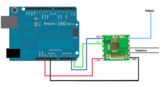
There are
several FM tuner chips. The Silicon labs SI4703 andSI4705, the Philips/NXP
TEA5700 family and the RDA RDA5807M radio tuners are easy to use in the Arduino
platform because we can use the Arduino library from Matthias Hertel.
But as often,
the RDS time could not be retrieved with this standard Arduino library.
The on website from R Hoerman I found coding I could use the read the time
from the RDS-signal.
He made plain
coding and with the RDS5807M Datasheet it was possible to write a RDS-time read
function
The chip
connects with an I2C protocol to the SDA and SCL lines A4 and A5 on the Arduino
UNO
An extract of
the code from Character_Clock_V095_328-1284_ZW-BT-FM-DCF.ino is below
The source
still needs a routine to find the best station with a proper time RDS-signal.
This routine
must continuously check if the best station is received.
Maybe two
‘best’ stations should be chosen. If they get out of sync the routine must
start a new scan to find the best stations again
For now the
best station can be set via Bluetooth or in the program it self.
// FM radio -----------------------
byte
RadioUur; // reading from RDS FM-radio
byte
RadioMinuut; // reading from RDS
FM-radio
float
fini = 103.50; //91.60; // 103.50; //98.10; // Start frequency
int
ftun; // Selected frequency
float
Freq_lower_bandwith = 87.00;// lower Band limit
float
Freq_tuned; //
int
RDA5807_adrs = 0x10; // I2C-Address RDA Chip for sequential Access
int
RDA5807_adrr = 0x11; // I2C-Address RDA Chip for random Access
int
RDA5807_adrt = 0x60; // I2C-Address RDA Chip for TEA5767like Access
int
sidx = 0; // Counter of frequency array
int
vol = 0; // Volume
int
rssi = 0; // Signal-Level
unsigned
int auRDS[32];
unsigned
int auRDA5807_Reg[32];
unsigned
int aui_RDA5807_Reg[32];
unsigned
int aui_buf[8];
unsigned
int auRDA5807_Regdef[10] ={
0x0758, // 00 defaultid
0x0000, // 01 not used
0xD009, // 02 DHIZ,DMUTE,BASS, POWERUPENABLE,RDS
0x0000,
// 03
0x1400, // 04 DE ? SOFTMUTE
0x84D0, // 05 INT_MODE, SEEKTH=0110,????, Volume=0
0x4000,
// 06 OPENMODE=01
0x0000, // 07 unused ?
0x0000, // 08 unused ?
0x0000 // 09 unused ?
};
// END FM radio ------------------------
//--------------------------------------------
//
Setup
//--------------------------------------------
void
setup()
{
Setup_FMradio();
}
//--------------------------------------------
//
Loop
//--------------------------------------------
void
loop(void)
{
FMradioCheck();
}
//--------------------------------------------
//
RDA5807 Setup_FMradio
//--------------------------------------------
void
Setup_FMradio(void)
{
RDA5807_PowerOn();
RDA5807_Reset();
RDA5807_setFreq(fini);
}
//--------------------------------------------
//
RDA5807 Reset Chip to Default Configuration
//--------------------------------------------
int
RDA5807_Reset()
{
Serial.println(F("RESET RDA5807"));
for(int i = 0;i < 7; i++) {auRDA5807_Reg[i] = auRDA5807_Regdef[i];}
auRDA5807_Reg[2] = auRDA5807_Reg[2] | 0x0002; // Enable SoftReset
int ret = RDA5807_Write();
auRDA5807_Reg[2] = auRDA5807_Reg[2] & 0xFFFB; // Disable SoftReset
return ret;
}
//----------------------------------------
//
RDA5807 Power Off
//----------------------------------------
int
RDA5807_PowerOff()
{
RDA5807_setVol(0);
Serial.println("Power OFF RDA5807");
aui_RDA5807_Reg[2]=0x0001; // all bits off
return RDA5807_Write();
auRDA5807_Reg[2] =auRDA5807_Regdef[2]; // Reset to Default Value
}
//----------------------------------------
//
RDA5807 Power On
//----------------------------------------
int
RDA5807_PowerOn()
{
Serial.println(F("Power ON RDA5807"));
auRDA5807_Reg[3] = auRDA5807_Reg[3] | 0x010; // Enable Tuning
auRDA5807_Reg[2] = auRDA5807_Reg[2] | 0x001; // Enable PowerOn
int ret = RDA5807_Write();
auRDA5807_Reg[3] = auRDA5807_Reg[3] & 0xFFEF; // Disable Tuning
return ret;
}
//----------------------------------------
//
RDA5807 Seek up to next Station
//----------------------------------------
int
RDA5807_SeekUp()
{
Serial.println(F("SeekUp"));
auRDA5807_Reg[2] = auRDA5807_Reg[2] | 0x0300; // Enable Seekup
RDA5807_Write();
auRDA5807_Reg[2] = auRDA5807_Reg[2] & 0xFCFF; // Disable Seekup
return 0;
}
//----------------------------------------
//
RDA5807 Seek down to next Station
//----------------------------------------
int
RDA5807_SeekDown()
{
Serial.println(F("SeekDown"));
auRDA5807_Reg[2] = auRDA5807_Reg[2] | 0x0100; // Enable SeekDown(default)
RDA5807_Write();
auRDA5807_Reg[2] = auRDA5807_Reg[2] & 0xFCFF; // Disable Seek
return 0;
}
//----------------------------------------
//
RDA5807 Tune Radio to defined Frequency
//----------------------------------------
int
RDA5807_setFreq(float mhz)
{
ftun = mhz * 100.0;
Freq_tuned = mhz;
int Chnumber = (int)(( 0.01 + mhz - Freq_lower_bandwith ) / 0.1);
Serial.print(F("Frequency: "));
Serial.print(ftun);
Serial.print(F(" Channel: "));
Serial.println(Chnumber);
Chnumber = Chnumber & 0x03FF;
auRDA5807_Reg[3] = Chnumber * 64 + 0x10; // Channel + TUNE-Bit +
Band=00(87-108) + Space=00(100kHz)
Wire.beginTransmission(RDA5807_adrs);
Wire_write16(0xD009);
Wire_write16(auRDA5807_Reg[3]);
Wire.endTransmission();
return 0;
}
//----------------------------------------
//
RDA5807 Set Volume
//----------------------------------------
int
RDA5807_setVol(int setvol)
{
vol = setvol;
if (vol > 15) {vol = 15; Serial.println(F("Vol already maximal"));
return 1; }
if (vol < 0) {vol = 0; Serial.println(F("Vol already minimal"));
return 1; }
Serial.print(F("Volume="));
Serial.println(vol);
auRDA5807_Reg[5]
= (auRDA5807_Reg[5] & 0xFFF0)| vol; // Set New Volume
RDA5807_WriteReg(5);
return 0;
}
//----------------------------------------
//
Write 16Bit To I2C / Two Wire Interface
//----------------------------------------
void
Wire_write16(unsigned int val)
{
//
if (b_debug) { Serial_print16h(val);}
Wire.write(val >> 8); Wire.write(val & 0xFF);
}
//------------------------------------------
//
Serial Print 16Bit Number in HEX as hh:ll
//------------------------------------------
void
Serial_print16h(unsigned int uval)
{
byte b_high,b_low;
b_high = uval >> 8; b_low = uval & 0xFF;
if (b_high < 0x10){ Serial.write('0');} Serial.print(b_high,HEX);
Serial.write(':');
if (b_low < 0x10){ Serial.write('0');} Serial.print(b_low ,HEX);
}
//----------------------------------------
//
RDA5807 Set all Configuration Registers
//----------------------------------------
int
RDA5807_Write()
{
Wire.beginTransmission(RDA5807_adrs);
for ( int i = 2; i < 7; i++) { Wire_write16(auRDA5807_Reg[i]);}
return Wire.endTransmission();
}
//----------------------------------------
//
RDA5807 Set one Configuration Registers
//----------------------------------------
int
RDA5807_WriteReg(int reg)
{
Wire.beginTransmission(RDA5807_adrr);
Wire.write(reg);
Wire_write16(auRDA5807_Reg[reg]);
return Wire.endTransmission();
}
//---------------------------------------------
//
RDA5807 Read Special Data Registers as Word
//---------------------------------------------
void
RDA5807_ReadW(int cnt)
{
Wire.beginTransmission(RDA5807_adrr); // Device 0x11 for random
access
Wire.write(0x0C); // Start at Register 0x0C
Wire.endTransmission(0); // restart condition
Wire.requestFrom(RDA5807_adrr,2*cnt, 1); // Retransmit device address
with READ, followed by 8 bytes
for
(int i = 0; i < cnt; i++) // Loop for Read data
{auRDS[i] = 256 * Wire.read() + Wire.read();} // Read Data
into Array of Unsigned Ints
Wire.endTransmission();
}
//----------------------------------------
//
RDA5807 Read and Show all Status Registers
//----------------------------------------
int
RDA5807_ReadStatus()
{
int Chnumber = -1;
unsigned int aubuf[8];
memset (aubuf, 0, 8);
Serial.println(F("Info Status RDA5807:"));
Serial.println(F("Reg | 0Ah | 0Bh | 0Ch | 0Dh | 0Eh | 0Fh |"));
Serial.print(F(" |"));
Wire.requestFrom(RDA5807_adrs, 12);
for (int i = 0; i < 6; i++) { aubuf[i] = 256 * Wire.read () + Wire.read();
}
Wire.endTransmission();
for (int i = 0; i < 6; i++) { Serial_print16h(aubuf[i]); Serial.print("|");
}
Serial.println();
Chnumber = (aubuf[0] & 0x03FF);
Freq_tuned = Freq_lower_bandwith + Chnumber * 0.10;
rssi = aubuf[1] >> 10;
Serial.print(F("RDS Data: ")); if ((aubuf[0] & 0x8000)==0){
Serial.println(F("NO"));} else {Serial.println(F("NEW
data"));}
Serial.print(F("SEEK Ready: ")); if ((aubuf[0] & 0x4000)==0){
Serial.println(F("no"));} else
{Serial.println(F("OK"));}
Serial.print(F("SEEK Fail: ")); if ((aubuf[0] & 0x2000)==0){
Serial.println(F("no, Succces!"));} else
{Serial.println(F("FAILED"));}
Serial.print(F("RDS Sync: ")); if ((aubuf[0] & 0x1000)==0){ Serial.println(F("no"));}
else {Serial.println(F("OK"));}
Serial.print(F("RDS Block: ")); if ((aubuf[0] & 0x0800)==0){
Serial.println(F("no"));} else
{Serial.println(F("Block E"));}
Serial.print(F("Stationmode: ")); if ((aubuf[0] & 0x0400)==0){
Serial.println(F("Mono "));} else
{Serial.println(F("Stereo"));}
Serial.print(F("Channel Nr: ")); Serial.print(Chnumber);
Serial.print(F(" = "));
Serial.print(Freq_tuned); Serial.println(F(" MHz"));
Serial.print(F("SignalLevel:
")); Serial.println(rssi);
return 0;
}
//----------------------------------------
//
RDA5807 Report all available Stations
//----------------------------------------
int
RDA5807_Report()
{
Freq_tuned = Freq_lower_bandwith;
int cnt_stations = 0;
int cnt_stereo = 0;
int cnt_rds = 0;
int Rssi = 0;
//auRDA5807_Reg[3]
= 0x10; //Set channelnumber 0
//RDA5807_setFreq(87.50);
Serial.println(F("Sender Report:"));
for(int Chnumber = 0; Chnumber <= 210; Chnumber++)
{
auRDA5807_Reg[3] = 64 * Chnumber + 0x10;
Wire.beginTransmission(RDA5807_adrs);
Wire_write16(0xD009);
Wire_write16(auRDA5807_Reg[3]);
Wire.endTransmission();
delay(300); //give de radio some time to settle
RDA5807_Status();
}
}
//----------------------------------------
//
RDA5807 Show Status
//----------------------------------------
void
RDA5807_Status(void)
{
int Chnumber;
Wire.requestFrom (RDA5807_adrs, 16);
for (int i = 0; i < 8; i++) { auRDA5807_Reg[0x0A + i] = 256 * Wire.read () +
Wire.read(); }
Wire.endTransmission();
Chnumber = auRDA5807_Reg[0x0A] & 0x03FF;
rssi = auRDA5807_Reg[0x0B] >> 10;
Freq_tuned = Freq_lower_bandwith + (Chnumber ) * 0.1;
//
if ( (auRDA5807_Reg[0x0A] & 0x8000) && (auRDA5807_Reg[0x0A] &
0x0400) ) // if RDS and stereo in station
if
((auRDA5807_Reg[0x0A] & 0x0400) ) // if Stereo in
station
{
if (Freq_tuned <= 99.99){Serial.print(" ");}
Serial.print(Freq_tuned);
Serial.print(F(" MHz"));
Serial.print(F(" Ch=")); if (Chnumber < 10){Serial.print(F("
"));} if (Chnumber < 100) { Serial.print(F(" ")); }
Serial.print(Chnumber);
Serial.print(F(" PI="));
Serial_printuih(auRDA5807_Reg[0x0C]); // RDS Block A contains
Station ID
if ((auRDA5807_Reg[0x0A] & 0x0400) == 0) { Serial.print(F(" Mono
"));} else { Serial.print(F(" Stereo"));}
if ((auRDA5807_Reg[0x0A] & 0x8000) == 0) { Serial.print(F("
---")); } else { Serial.print(F(" RDS")); }
Serial.print(F(" Sig= ")); if (rssi < 10) {
Serial.print(F(" ")); } else Serial.print(rssi);
Serial.print(F(" "));
for(int
i = 0; i < rssi - 5; i++) { Serial.print(F("*")); }
Serial.println();
}
}
//----------------------------------------
//
RDA5807 Show Status
//----------------------------------------
void
RDA5807_Get_RSSI()
{
Wire.requestFrom (RDA5807_adrs, 16);
for (int i = 0; i < 8; i++) { auRDA5807_Reg[0x0A + i] = 256 * Wire.read () +
Wire.read(); }
Wire.endTransmission();
rssi = auRDA5807_Reg[0x0B] >> 10;
}
//----------------------------------------
//
SerialPrint 16Bit Number in HEX as hhll
//----------------------------------------
void
Serial_printuih(unsigned int val)
{
if (val < 0xF) Serial.print(F("0")); // if less
2 Digit
if (val < 0xFF) Serial.print(F("0")); // if less
3 Digit
if (val < 0xFFF) Serial.print(F("0")); // if less
4 Digit
Serial.print(val,HEX);
Serial.print(F(" "));
}
//----------------------------------------
//
RDA5807 Radio Data System Dump Infos
//----------------------------------------
int
RDA5807_RDS_Dump()
{
Serial.println(" PI |GTxx|Asci");
while(Serial.available()==0)
{
RDA5807_ReadW(4); // Read RDS-Data as 4 Word to
Array
if((auRDS[1] & 0xF000)==0x2000)
{
//
Serial_printuih(auRDS[0]); // Block A PI
//
Serial_printuih(auRDS[1]); // Block B GT(5Bit)T(1Bit)
PTY(5Bit)POS(5)Bit
//
Serial_printuih(auRDS[2]);
//
Serial_printuih(auRDS[3]);
//
int x = 16 + 4*(auRDS[1] & 0x000F);
for (int i=2;i<4;i++)
{
Serial.write(auRDS[i]>>8); // Block C/D Ascii Code
Serial.write(auRDS[i]&0xFF); // 2 * 2 Byte
}
}
if ((auRDS[1] & 0xF000)==0x4000)
{
int i_hh =(16*(auRDS[2] & 0x0001)+((auRDS[3] & 0xF000)>>12));
int
i_mm =(auRDS[3] & 0x0FC0)>>6;
int i_ofs=(auRDS[3] & 0x003F);
i_hh=i_hh+(i_ofs/2);
if (i_hh <10){Serial.write(' ');} Serial.print(i_hh); Serial.write(':');
if (i_mm <10){Serial.write('0');} Serial.print(i_mm); Serial.write(' ');
}
if ((auRDS[1]& 0xF000)==0x400)
{
Serial.print(F("RDS CT: ")); for (int i=0;i<4;i++){
Serial_print16h(auRDS[i]); Serial.write(' | ');} Serial.println();
}
delay(80);
Serial.println();
}
return 0;
}
//----------------------------------------
//
RDA5807 Radio Data System Dump Infos
//----------------------------------------
int
RDA5807_RDS_DumpCT()
{
int i_gt,i_gab,i_pty,i_t,i_pos,i_hh,i_mm,i_ofs;
RDA5807_Status();
Serial.println(F(" PI |GTxx|Asci GT T PTY POS HH:mm Offset"));
while(Serial.available()==0)
{
RDA5807_ReadW(4); // Read RDS-Data as 4 Word to
Array
i_gt = auRDS[1] >>12;
if ((auRDS[1] & 0x0800)==0){i_gab='A';} else {i_gab='B';}
i_t =(auRDS[1] & 0x0400)>10;
i_pty=(auRDS[1] & 0x03FF)>>5;
i_pos=(auRDS[1]
& 0x000F);
i_hh =(16*(auRDS[2] & 0x0001)+((auRDS[3] & 0xF000)>>12));
i_mm
=(auRDS[3] & 0x0FC0)>>6;
i_ofs=(auRDS[3] & 0x003F);
i_hh=i_hh+(i_ofs/2);
if (i_gt==4)
{
Serial_printuih(auRDS[0]); // Block A PI
Serial_printuih(auRDS[1]); // Block B GT(4Bit) A/B(1Bit) T(1Bit) PTY(5Bit)POS(5)Bit
Serial_printuih(auRDS[2]);
Serial_printuih(auRDS[3]);
if (i_gt <10){Serial.write(' ');} Serial.print(i_gt); Serial.write(i_gab);
Serial.write(' ');
if (i_t <10){Serial.write(' ');} Serial.print(i_t); Serial.write(' ');
if (i_pty<10){Serial.write(' ');} Serial.print(i_pty); Serial.print("
");
if (i_pos<10){Serial.write(' ');} Serial.print(i_pos); Serial.write("
");
if (i_hh <10){Serial.write(' ');} Serial.print(i_hh); Serial.write(':');
if (i_mm <10){Serial.write('0');} Serial.print(i_mm); Serial.write(' ');
Serial.print(i_ofs);
Serial.println();
}
delay(80);
}
return 0;
}
A GPS gives a
very exact time. There are two drawbacks. A GPS must see the sky for a proper
signal and winter and summer time should be programmed.
A good tutorial
can be found here:
http://playground.arduino.cc/Tutorials/GPS
Use the Bluetooth
HC-05 and HM-10 4.0 BT-BLE modules to send and receive messages
Communication
with Bluetooth modules takes place through the serial pin RX and TX on the
ATMEGA chip
The library
Softwareserial.h makes it possible to use other pins than the standard pins 0
and 1 that are also used to upload programs.
The HC-05
module is very cheap but cannot connect to Apple devices.
The identical
looking HM-10 module can connect to Apple
and Android devices.
See more about app et cetera here:
BLESerialUsage
Below is a
method to
change the name in a HC-05 Bluetooth-module:
First we need
to connect the HC-05 module to an Arduino.
Connect VCC to 3.3V on the Arduino and GND
to GND, connect pin 6 to TXD and pin 7 to RXD on the Bluetooth-module.
So RX goes to TX and TX is connected to RX;
“the wires are crossed”
The module has a default name like HC-05.
First we will change that name.
Load the following sketch into the Arduino:
-------------------------
#include<
SoftwareSerial.h>
SoftwareSerial
BTSerial(6, 7); // RX | TX
void setup()
{
pinMode(9,
OUTPUT); // this pin will pull the HC-05 pin 34 (key pin) HIGH to switch
module to AT mode
digitalWrite(9, HIGH);
Serial.begin(9600);
Serial.println("Enter AT commands:");
BTSerial.begin(38400); // HC-05 default speed in AT command more
}
void loop()
{
// Keep
reading from HC-05 and send to Arduino Serial Monitor
if
(BTSerial.available())
Serial.write(BTSerial.read());
// Keep
reading from Arduino Serial Monitor and send to HC-05
if
(Serial.available())
BTSerial.write(Serial.read());
}
---------------------------------
Detach the USB-cable to make the module
powerless.
Connect a thin wire between 3.3V of the
Arduino and pin 34. (Top right of the Bluetooth-module when the connection pins
are pointing down)
Connect the Arduino to the PC, start the
Arduino IDE programmer and open “Serial monitor”.
The red LED of the Bluetooth-module start
blinking 2sec on, 2 sec off.
Enter in the Serial monitor:
AT à
OK
AT+NAMEDevice01 (Or any other name you like
to give the module)
AT+RESET
The passkey of the module = 1234 when you
connect

Here is a
method to
change the name in a HM-10 4.0 BT-BLE Bluetooth-module:
First we need
to connect the HM10-module to an Arduino.
Connect VCC to 3.3V on the Arduino and GND
to GND, connect pin 6 to TXD and pin 7 to RXD on the Bluetooth-module.
So RX goes to TX and TX is connected to RX;
“the wires are crossed”
The module has a default name like CC41-A. First
we will change that name.
Load the following sketch into the Arduino
Uno:
-------------------------
#include
<SoftwareSerial.h>
SoftwareSerial
mySerial(6, 7); // RX, TX
// Connect
HM10 Arduino Uno
// Pin TXD Pin
6
// Pin RXD Pin
7
void setup() {
Serial.begin(9600);
// If the
baudrate of the HM-10 module has been updated,
// you may need
to change 9600 by another value
// Once you
have found the correct baudrate,
// you can
update it using AT+BAUDx command
// e.g. AT+BAUD0
for 9600 bauds
mySerial.begin(9600);
}
void loop() {
char c;
if
(Serial.available()) {
c =
Serial.read();
mySerial.print(c);
}
if
(mySerial.available()) {
c =
mySerial.read();
Serial.print(c);
}
}
Start the
serial monitor in the Arduino IDE.
Change right
under in the monitor the LF&CR settings to “No line ending” and the baud
rate to 9600 Baud
Enter in the
Serial monitor:
AT+RESET
AT+NAMEDevice01
(Or any other name you like to give the module)
AT+RESET
The passkey of
the module = 0000 when you pair the devices
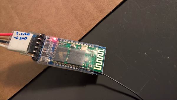
Fake HM10
modules, bottom one, lack a crystal.
The fake ones
cannot be programmed as described above.

Part of example
code
//--------------------------------------------
// BLUETOOTH
//--------------------------------------------
// Bluetooth ---------------------
SoftwareSerial
Bluetooth(6, 7); // RX, TX
String BluetoothString;
//--------------------------------------------
// Check for
Bluetooth input
//--------------------------------------------
void
BluetoothCheck(void)
{
while
(Bluetooth.available())
{
delay(3);
char c =
Bluetooth.read();
if (c>31
&& c<128) BluetoothString += c;
}
if
(BluetoothString.length()>0) ReworkInputString(BluetoothString);
BluetoothString
= "";
}
//--------------------------------------------
// Input from Bluetooth
or Serial
//--------------------------------------------
void
ReworkInputString(String InputString)
{
String temp;
float ff;
Serial.println(InputString);
if ( InputString[0]
> 64 )
{
int val = InputString[0];
switch (val)
{
case 'A':
case 'a':
Serial.println(F("A
was the first character"));
break;
case 'B':
case 'b':
Serial.println(F("B was the first character"));
break;
case 'C':
case 'c':
Serial.println(F("C was the first character"));
break;
case 'F':
case 'f':
//set
FM frequency
temp
= InputString.substring(1);
FMfreq = temp.toInt();
if (FMfreq
< 8750 ) FMfreq = 8750;
if
(FMfreq > 10800) FMfreq = 10800;
RDA5807_setFreq((float) FMfreq/100);
break;
default:
break;
}
InputString =
"";
}
}
The easiest
method to change or program a HM-10 module is using a FTDI programmer.
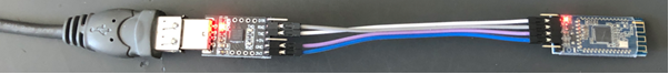 Connect the 3.3V and
GND and TX to RX and RX to TX.
Connect the 3.3V and
GND and TX to RX and RX to TX.
Open an serial monitor like Termite or de
Arduino Serial monitor and open the serial port
Enter AT in the monitor and OK should show up in the window as response of the
module
AT+NAME followed with the desired name give the module a new broadcasting name.
AT+HELP list the following commands:
********************************************************************
*
Command Description *
*
---------------------------------------------------------------- *
*
AT Check if the command terminal work normally *
*
AT+RESET Software reboot *
*
AT+VERSION Get firmware, bluetooth, HCI and LMP version *
*
AT+HELP List all the commands *
*
AT+NAME Get/Set local device name *
*
AT+PIN Get/Set pin code for pairing *
*
AT+PASS Get/Set pin code for pairing *
*
AT+BAUD Get/Set baud rate *
*
AT+LADDR Get local bluetooth address *
*
AT+ADDR Get local bluetooth address *
*
AT+DEFAULT Restore factory default *
*
AT+RENEW Restore factory default *
*
AT+STATE Get current state *
*
AT+PWRM Get/Set power on mode(low power) *
*
AT+POWE Get/Set RF transmit power *
*
AT+SLEEP Sleep mode *
*
AT+ROLE Get/Set current role. *
*
AT+PARI Get/Set UART parity bit. *
*
AT+STOP Get/Set UART stop bit. *
*
AT+START System start working. *
*
AT+IMME System wait for command when power on. *
*
AT+IBEA Switch iBeacon mode. *
*
AT+IBE0 Set iBeacon UUID 0. *
*
AT+IBE1 Set iBeacon UUID 1. *
*
AT+IBE2 Set iBeacon UUID 2. *
*
AT+IBE3 Set iBeacon UUID 3. *
*
AT+MARJ Set iBeacon MARJ . *
*
AT+MINO Set iBeacon MINO . *
*
AT+MEA Set iBeacon MEA . *
*
AT+NOTI Notify connection event . *
*
AT+UUID Get/Set system SERVER_UUID . *
*
AT+CHAR Get/Set system CHAR_UUID . *
*
-----------------------------------------------------------------*
*
Note: (M) = The command support slave mode only. *
*
For more information, please visit http://www.cyobd.com *
*
Copyright@2013 www.cyobd.com. All rights reserved. *
********************************************************************
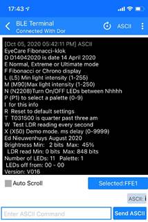
Communicate with
Android, Windows and Apple devices
With a HM10 BLE module the clock
can communicate with Apple IOS
and Android.
With a serial terminal program one
can send commands to the receiver that can be used in the Arduino program to do
something.
I use letters and digits to do some task in the program
const byte MenuItems = 23;              // sentences, rows, in menu
const char menu[MenuItems][MAXTEXT] = {
 "Woordklok",
 "Enter time as: hhmmss (132145)",
 "A Debug DCF-signal",
 "D D15122017 is date 15 December 2017",
 "G DCF-signalinfo in display",
 "H Use DCF-receiver",
 "L (L5) Min lightintensity(0-255 bits)",
 "M (M90)Max lightintensity(1%-250%)",
 "N (N2208)Turn On/OFF LEDs between Nhhhh",
 "P (P00234F8A) own colour (n=0-F)",
 "Q Display Choice (Q0-6)",
 "  Q0= Yellow colour, HETISWAS changing",
 "  Q1= Hourly colour",
 "  Q2= All white",
 "  Q3= All Own colour",
 "  Q4= Own colour, HETISWAS changing",
 "  Q5= Wheel colour",
 "  Q6= Digital display",
 "I For this info",
 "R Reset to default settings",
 "S Self test",
 "X (X50) Demo mode. ms delay (0-9999)",
 "Ed Nieuwenhuys sep 2020" };
There are commands that toggles a state but one can
also send a more information in the string.
void ReworkInputString(String InputString)
{
 String temp;
 InputString.toCharArray(sptext, MAXTEXT-1);
// Tekstprintln(sptext);
  Serial.println(InputString);
  if (InputString.length() >10) return;

 if(  InputString[0] > 64 && InputString[0] <123 )                     // Does the string start with a letter?
  {
//   Tekstprintln(sptext);
   switch ((byte)InputString[0])
   {
    case 'A':
    case 'a':
            if (InputString.length() == 1)
              {
               PrintDebugInfo = 1 - PrintDebugInfo;
               sprintf(sptext,"See DCF debug info: %s",PrintDebugInfo ? "On" : "Off");
               Tekstprintln(sptext);
              }
             else Tekstprintln("**** Length fault. Enter A ****");
             break;
    case 'D':
    case 'd':
            if (InputString.length() == 9 )
              {
               int Jaar;
               temp   = InputString.substring(1,3);     Iday = (byte) temp.toInt();
               temp   = InputString.substring(3,5);   Imonth = (byte) temp.toInt();
               temp   = InputString.substring(5,9);     Jaar =  temp.toInt();
               Iday   = constrain(Iday  , 0, 31);
               Imonth = constrain(Imonth, 0, 12);
               Jaar   = constrain(Jaar , 1000, 9999);
               RTCklok.adjust(DateTime(Jaar, Imonth, Iday, Inow.hour(), Inow.minute(), Inow.second()));
               sprintf(sptext,"%0.2d:%0.2d:%0.2d %0.2d-%0.2d-%0.4d",Inow.hour(),Inow.minute(),Inow.second(),Iday,Imonth,Jaar);
               Tekstprintln(sptext);
              }
            else Tekstprintln("**** Length fault. Enter ddmmyyyy ****");
            break;
------> and so on
There are hardly any apps or programs that can
communicate with the BLE devices.
Below one for IOS and one for Android.
Adafruit has a terminal for IOS and android:
https://learn.adafruit.com/bluefruit-le-connect/uart-terminal
This
app only works with the Adafruit devices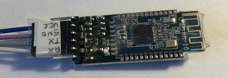 .
.
If the HM-10 or JDY-23 modules are used you
need one of apps mentioned below.
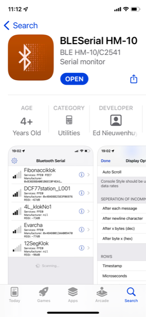
For Apple IOS
my program
"BLEserial
HM-10" from the app store can be used.
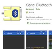
Serial Bluetooth Terminal van Kai Morich works fine as
terminal on Android.
For Windows 10 I can not find a
workable program.
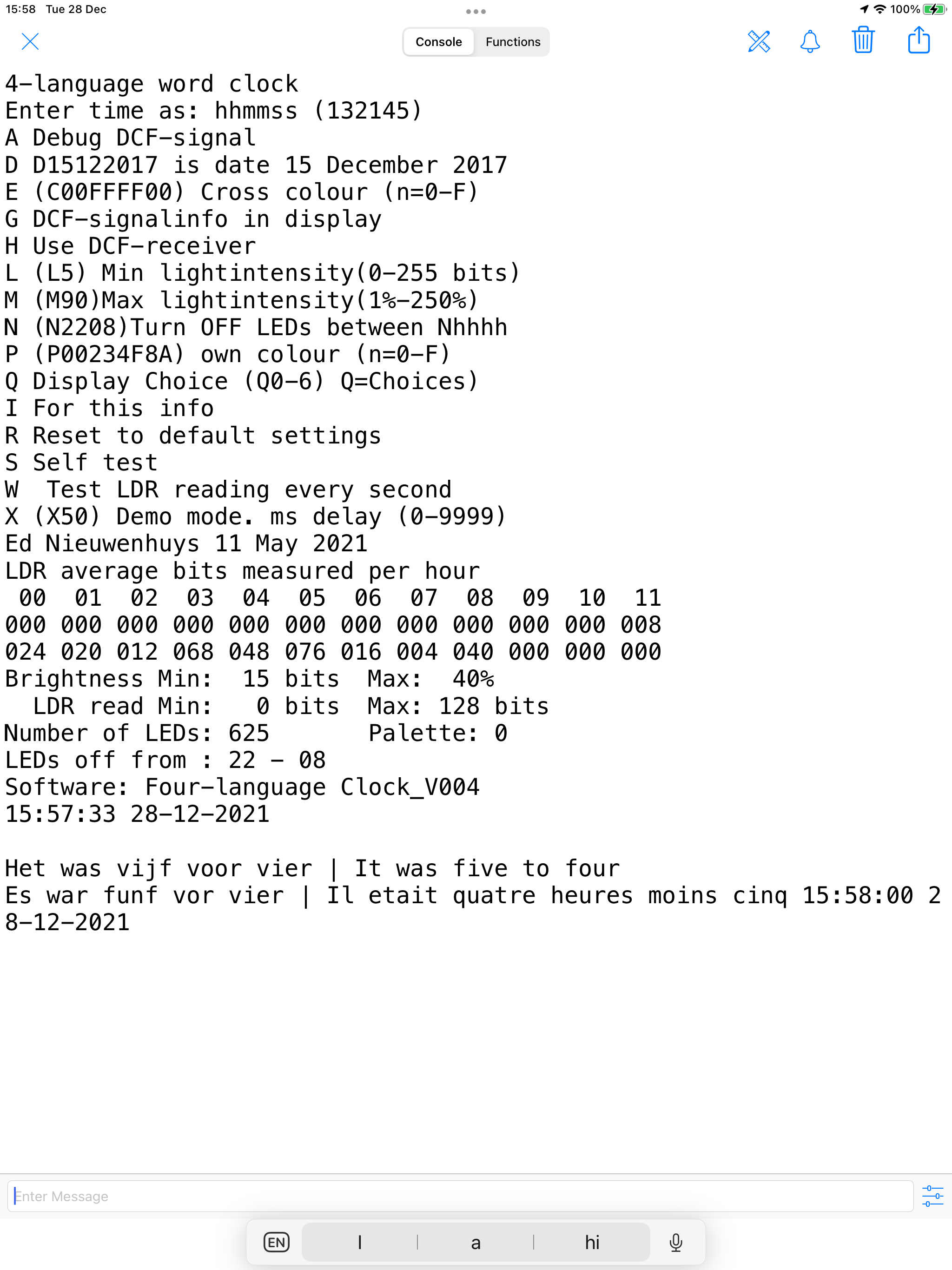
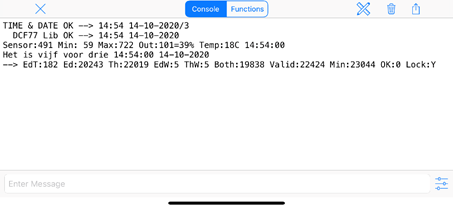
Connect in the app with your
HM-10 module.
Type a command in
the send of enter message box or wait if your program logs results in the
console window.
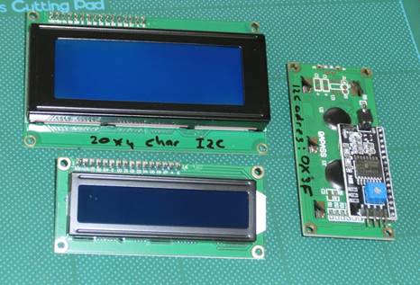
Communicate with
a LCD display
LCD displays
with 2x16 or 4x20 characters are very cheap and easy to use for displaying
information generated by the program when the serial monitor is not available
anymore.
We can buy them
with an I2C communication module attached to it. Without this module the
display can also be used but uses six connections and misses the advances I2C
that allows us to chain more devices on the two I2C lines.
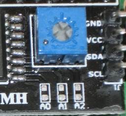
I2C uses unique
addresses for the communication with the I2C devices. 0X27, 0X3F, 0X38
On the I2C
module it is possible to change the device address by closing the solder pads
A0, A1 or A2. Default they are all open.
Above the pads
there is the contrast control.
When you buy the
displays you often do not know the device address. With the I2C scanner program
below it is possible to retrieve this address.
|
|
A0
|
A1
|
A2
|
HEX Address
|
|
O
|
O
|
O
|
0x27
|
|
C
|
O
|
O
|
0x26
|
|
O
|
C
|
O
|
0x25
|
|
C
|
C
|
O
|
0x24
|
|
O
|
O
|
C
|
0x23
|
|
C
|
O
|
C
|
0x22
|
|
O
|
C
|
C
|
0x21
|
|
C
|
C
|
C
|
0x20
|
O = open, C = closed
|
|
|
|
// I2C Scanner
//
Written by Nick Gammon
//
Date: 20th April 2011
#include
<Wire.h>
void
setup() {
Serial.begin
(115200);
//
Leonardo: wait for serial port to connect
while (!Serial)
{
}
Serial.println
();
Serial.println
("I2C scanner. Scanning ...");
byte
count = 0;
Wire.begin();
for
(byte i = 8; i < 120; i++)
{
Wire.beginTransmission (i);
if
(Wire.endTransmission () == 0)
{
Serial.print
("Found address: ");
Serial.print
(i, DEC);
Serial.print
(" (0x");
Serial.print
(i, HEX);
Serial.println
(")");
count++;
delay (1); // maybe unneeded?
} // end of good response
} //
end of for loop
Serial.println
("Done.");
Serial.print
("Found ");
Serial.print
(count, DEC);
Serial.println
(" device(s).");
} //
end of setup
void
loop() {}
Display on a 8 Digit LED
Display MAX7219 7 Segment Digital Tube
With this cheap
and easy to program breakout board it is easy to display numeric data. The
board uses an MAX7219 chip.
With the used
internal Arduino IDE library one can chain up to eight daisy chained MAX72XX
drivers.
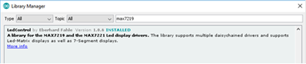
Install the
library “LedControl” available in the Arduino IDE library manager
//We
always have to include the library
#include
"LedControl.h"
/*
Now
we need a LedControl to work with.
*****
These pin numbers will probably not work with your hardware *****
pin
12 is connected to the DataIn (DIN)
pin
11 is connected to the CLK
pin
10 is connected to LOAD (CS)
We
have only a single MAX72XX.
*/
LedControl
lc = LedControl(12,11,10,1);
/*
we always wait a bit between updates of the display */
unsigned
long delaytime = 500;
void
setup() {
/*
The MAX72XX is in power-saving mode on startup,
we have to do a wakeup call
*/
lc.shutdown(0,false); // Set the brightness to a medium values
lc.setIntensity(0,2); // and clear the display
lc.clearDisplay(0);
}
void
loop()
{
char text[8];
int n = sprintf(text,"%8ld", millis() );
setDisplayToString(text);
}
//
The setChar(addr,digit,value,dp)-function accepts a value of type char for the
//
in the range of a 7-bit ASCII encoding. Since the recognizable patterns are
limited,
//
most of the defined characters will print the <SPACE>-char.
//
But there are quite a few characters that make sense on a 7-segment display.
//
Display a character on a 7-Segment display.
//
Params:
//
addr = address of the display (0 - 7)
//
digit = the position of the character on the display (0..7)
//
value = the character to be displayed.
//
dp = sets the decimal point.
void
setDisplayToString(char text[])
{
for(byte
n=0;n<8;n++) lc.setChar(0,7-n, text[n] ,(n==4?1:0)); //decimal point at 4th
char
}
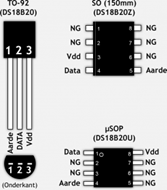
Add a temperature
sensor Dallas DS1820
At Tweaking4all a detailed description can be read.
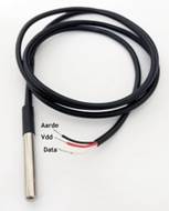
With the Dallas
DS1820 temperature sensors it is easy to measure temperature.
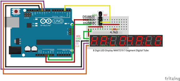
Up to 16 (or
more?) sensors can be chained. If many sensors are chained the 4.7 kOhm
resistor must be replaced with a lower resistance resistor.
Several types
of sensor can be bought.
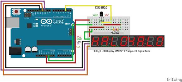
In
this example the temperature of the Dallas DS1820 sensor is displayed on an 8
Digit LED Display MAX7219 7 Segment Digital Tube.
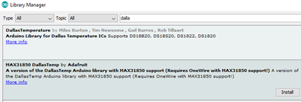
Install the
Onewire, LedControl and MAX31850 library in the library manager of the Arduino
IDE.
Connect the display and temperature reader as shown.
Or
chained them up.
Load
the source code.
#include
<LedControl.h>
#include
<OneWire.h>
#include
<DallasTemperature.h>
LedControl
lc = LedControl(12,11,10,1); // pin 10 is connected to LOAD,
pin 11 to CLK, pin 12 to DataIn
#define
ONE_WIRE_BUS 2 // Data wire is plugged into
port 2 on the Arduino
#define
TEMPERATURE_PRECISION 12 // a DS18B20 takes from 94ms
(9-bit resolution) to 750ms (12-bit resolution) to convert temperature
OneWire
oneWire(ONE_WIRE_BUS); // Setup a oneWire instance to
communicate with any OneWire devices
DallasTemperature
Tempsensors(&oneWire); // Pass our oneWire reference to
Dallas Temperature.
int
numberOfDevices; // Number of temperature
devices found
DeviceAddress
tempDeviceAddress; // We'll use this variable to store
a found device address
//-------------------------------------------------------------------------------------------
void
setup() {
lc.shutdown(0,false); // The MAX72XX is in
power-saving mode on startup, we have to do a wakeup call
lc.setIntensity(0,2); // Set the brightness to
a medium values
lc.clearDisplay(0); // and clear the display
Serial.begin(9600); // start serial port
Tempsensors.begin(); // Start up the library
numberOfDevices = Tempsensors.getDeviceCount(); // Grab a count of
devices on the wire
Serial.print("Found "); Serial.print(numberOfDevices, DEC);
Serial.println(" devices.");
Serial.print("Parasite power is: "); // report
parasite power requirements
if (Tempsensors.isParasitePowerMode()) Serial.println("ON");
else Serial.println("OFF");
for(int i=0;i<numberOfDevices; i++) // Loop through each
device, print out address
{
if(Tempsensors.getAddress(tempDeviceAddress, i)) // Search the wire for
address
{
Serial.print("Found device "); Serial.print(i, DEC);
Serial.print(" with address: "); printAddress(tempDeviceAddress);
Serial.println();
Serial.print("Setting resolution to ");
Serial.println(TEMPERATURE_PRECISION, DEC);
Tempsensors.setResolution(tempDeviceAddress, TEMPERATURE_PRECISION);
delay(100);
Serial.print("Resolution actually set to: "); Serial.print(Tempsensors.getResolution(tempDeviceAddress),
DEC); Serial.println();
}
else
{
Serial.print("Found ghost device at "); Serial.print(i,
DEC);
Serial.println(" but could not detect address. Check power and
cabling");
}
}
}
//-----------------------------------------------------------------------------------
void
loop()
{
char text[8];
Tempsensors.requestTemperatures(); // Send the command to
get temperatures
for(int i=0;i<numberOfDevices; i++) // Loop through each
device, print out temperature data
{
if(Tempsensors.getAddress(tempDeviceAddress, i)) // Search the wire for
address
{
Serial.print("Temperature for device: "); Serial.print(i,DEC);
// Output the device ID
Serial.print(" Temp C: ");
Serial.println(Tempsensors.getTempC(tempDeviceAddress));
sprintf(text,"%8ld", (long) (10 *
Tempsensors.getTempC(tempDeviceAddress)) );
setDisplayToString(text,1);
} //else ghost device! Check
your power requirements and cabling
}
delay(2000);
}
//-------------------------------------------------------------------------------
//
addr-address of the display (0 - 7),digit-position of the character on the
display(0..7)
//
value-the character to be displayed, dp - sets the decimal point.
void
setDisplayToString(char text[],byte Posdot)
{
for(byte
n = 0; n < 8; n++)
lc.setChar(0,7-n,
text[n] ,(n==(7-Posdot)?1:0)); // No of Posdot decimal positions
}
//
function to print a device address
void
printAddress(DeviceAddress deviceAddress)
{
for (uint8_t i = 0; i < 8; i++)
{
if (deviceAddress[i] < 16) Serial.print("0");
Serial.print(deviceAddress[i], HEX);
}}
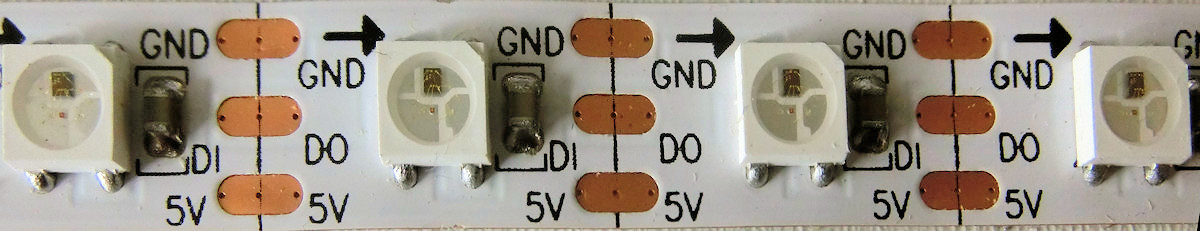
The WS2812 RGB colour LEDs
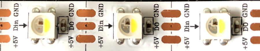
and the SK6812 RGBW colour LEDS with an additional
white LED.
Both LED types can be bought as strip. The signal enters
at Di or Din and leaves at Do (Dout)
Every chip has a number starting at zero and
the following is a number higher. In the program you can set the colour of
every chip with a chip number and the RGB(W) value.
For the WS2812 I use
the light weight library to control WS2811/WS2812 based
LEDS and LED Strings for 8-Bit AVR microcontrollers.
https://github.com/cpldcpu/light_ws2812
For the SK6812 Adafruit_NeoPixel
is used. https://github.com/adafruit/Adafruit_NeoPixel
This can be installed from the Arduino library in the IDE.
I rewrote a WS2812 library to be used for the SK6812
LEDs.
All libraries I have tested use program memory but the bytes are
not written off in the compiler. In other words, after compiling the IDE
reports: "Sketch uses 26496 bytes (82%) of program storage space. Maximum is
32256 bytes."
But suddenly your Arduino starts restarting or in my case
serial input was not processed in the program. It seems memory used for the
LEDs are overwriting program memory.
I tried to solve this by allocating
memory not with a 'malloc' but with 'new' keyword.
Alas, it was no
solution but library is smaller than the Neopixel.
https://github.com/ednieuw/EdSoft_SK6812
SK6812 LEDs are
superior to the WS2812 LEDs. They contain a extra white LED.
Beside this the SK6812 can also be used
instead of white 2835 or 3528 white LED strips. A little more
expensive but these LEDs can be addressed independent with one single
pin of the Arduino.
Initialize an array of 32
bytes
byte LDRread[32]; // Store average
LDR-readings/4 per hour in this array
Clear the array
for (int i=0;i<32;i++) LDRread[i] = 0; // Reset
readings
Read the data to NVRAM
DS3231NVRAMRead(0,LDRread); // Read the LDR
reading from NVRAM DS3231 clock module if present
Write the data to NVRAM
DS3231NVRAMWrite(0,LDRread);
//--------------------------------------------
//
EEPROM DS3231 Read NVRAM at I2C address 0x57
// The size of the NVRAM is
32 bytes
//--------------------------------------------
template
<class T> int DS3231NVRAMWrite(int EEPROMaddress, const T& value)
{
const byte* p = (const byte*)(const void*)&value;
unsigned int i,x;
for (x=0; x< sizeof(value)/32 +1; x++) // Write in blocks of 32 bytes
{
Wire.beginTransmission(0x57);
Wire.write((int)(EEPROMaddress >> 8)); //
MSB
Wire.write((int)(EEPROMaddress & 0xFF)); // LSB
for (i = 0; i <
32; i++) Wire.write(*p++);
Wire.endTransmission();
delay(5);
//
sprintf(sptext,"Size:%d writeP: %d x:%d",sizeof(value), p, x); Tekstprintln(sptext);
}
return i;
}
//--------------------------------------------
// EEPROM DS3231 Write NVRAM at I2C address 0x57
// The size of the NVRAM
is 32 bytes
//--------------------------------------------
template <class T> int DS3231NVRAMRead(int EEPROMaddress, T& value)
{
byte* p = (byte*)(void*)&value;
unsigned int i,x;
for (x=0; x< sizeof(value)/32
+1; x++) // Read in blocks of 32 bytes
{
Wire.beginTransmission(0x57);
Wire.write((int)(EEPROMaddress >> 8)); // MSB
Wire.write((int)(EEPROMaddress
& 0xFF)); // LSB
Wire.endTransmission();
Wire.requestFrom(0x57,32);
for (i = 0; i<32; i++) {if(Wire.available()) *p++ = Wire.read(); }
delay(5);
// sprintf(sptext,"Size:%d readP; %d x:%d",sizeof(value), p,
x); Tekstprintln(sptext);
}
return i;
}
Like pins. A/D
and digital pin
PWM
Bit Shift
registers
Controlling
B/W LED’s
Controlling
WS2812 LEDS
<--Back
Ed Nieuwenhuys.
1 may 2022