<--
Home
This pages describes the characteristics of the GL55-series photo
resistors.
Photo resistors
or LDRs (Light Depended Resistor) are used to detect photons.
The more
photons, the more luminous, the lower the resistance of this passive element
becomes.
With an analogue port of an Arduino or other microcontroller the
resistance can converted to a value and the rest is coding.
It is not
always obvious but there are several types of LDRs.
The ones described here are
cheap and easy available; the GL-5xxx serie with a diameter of 5 mm.
Often the LDR type is not mentioned and which
one is received is a surprise.
The difference between the types
is the resistance characteristics at different luminous intensities
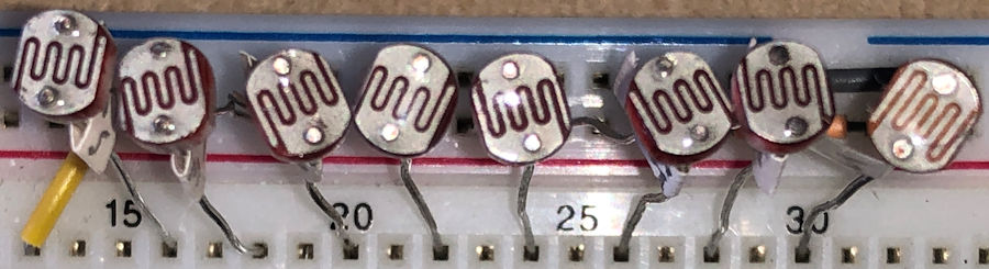
I used the following LDRs bought as a set:GL5506 GL5516 GL5528 GL5537 GL5539
GL5549
Beside these LDRs I had GL5528 LDRs I regularly use in my
designs.
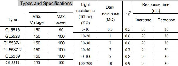
Datasheet
The datasheet gives to following specs. Power is probably mW or uW but the unit
is not mentioned
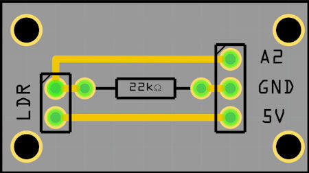
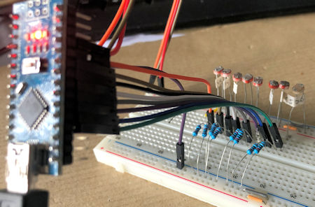
| Connections Eight LDRs were connected via A2 on the PCB to analogue ports A0 - A7 on the Arduino as shown below with a 22 kohm or a 10 kohm resistor. The higher the resistance the less power is lost in the design. Because a 10K resistor is used in many designs this resistor may be preferred to avoid using many different parts in your design. |
|
 |
 |
Software
unsigned long sensorValue[7] = {0}; // variable to store the value coming from the sensor
char sptext[80];
void setup()
{
Serial.begin(115200);               // Setup the serial port to 9600 baud
while (!Serial);                    // Wait for serial port to connect. Needed for native USB port only
sprintf(sptext,"g506 g516 g528 g528 g528 g537 g539 g549 Min Max ",
sensorValue[0],sensorValue[1],sensorValue[2],sensorValue[3],
sensorValue[4],sensorValue[5],sensorValue[6],sensorValue[7]);
Serial.println(sptext);
}

void loop()
{
long NoLoops=320;                   // Max 32000 loops
for(int i=0; i<8; i++) sensorValue[i] = 0;
for(int n=0; n<NoLoops; n++) for(int i=0; i<8; i++) sensorValue[i] += analogRead(i);
for(int i=0; i<8; i++) sensorValue[i] /= NoLoops;

sprintf(sptext,"%0.4ld %0.4ld %0.4ld %0.4ld %0.4ld %0.4ld %0.4ld %0.4ld 0000 1000",
sensorValue[0],sensorValue[1],sensorValue[2],sensorValue[3],
sensorValue[4],sensorValue[5],sensorValue[6],sensorValue[7]);
Serial.println(sptext);
}
| Results | ||||||||||
| The first results shows that in one batch of identical LDRs there can be a great variation. With the 22k resistor the following bits were recorded:
|
 |
|||||||||
 |
||||||||||
| GL5506 (top line) GL5516 GL5528 GL5537 GL5539 GL5549 | ||||||||||
 |
||||||||||
| GL5506 GL5516 GL5528 GL5537 GL5539 GL5549 (bottom line) | ||||||||||
The results in the pictures above were sampled for several hours until it was
dark outside.
The left graph shows the results with a 10 kOhm resistor in the design and the
right graph with a 22kOhm resistor
The GL5537 and GL5539 are so comparable that they switched from the expected
position in the graph.
Two GL5528 LDR (gray and yellow lines) are plotted in the graph and they show similar behavior to
luminously.
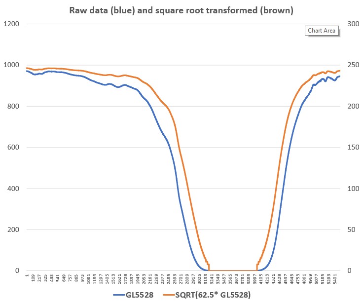
When using
LDRs to control the intensity of LED displays your pupil becomes larger and
adapts to the darkness.
Using the direct readings from the analogue port results in LEDs
to bright in the dark and not bright enough in full light.
Taking the
square root of the measured_value * 62.5 gives a transformed result between 0
and 255
compensates this effect in my designs when using the GL-5528 with a
22K resistor successful.
26 jan 2021
Mail: Ed Nieuwenhuys