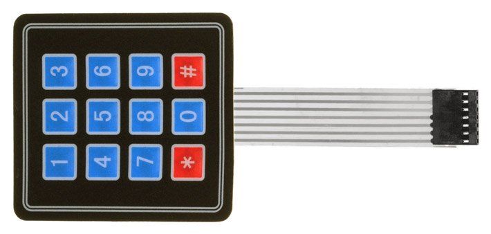
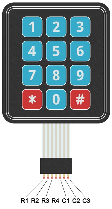
- seven pins, 3 columns * 4 rows key pad
and a
to a one wire analogue output.
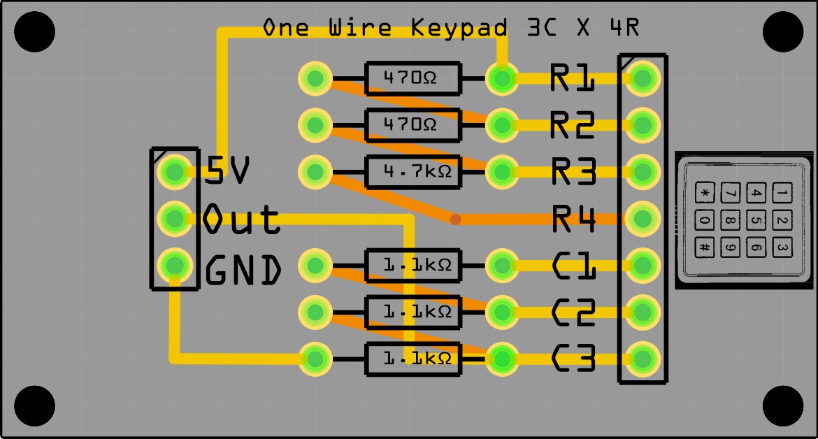
One Wire Key Pad
|
This page describes how to wire the output pins of a: - seven pins, 3 columns * 4 rows key pad and a |
|
|
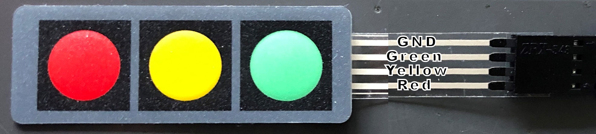
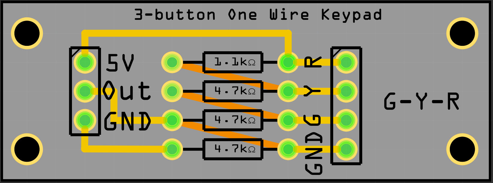
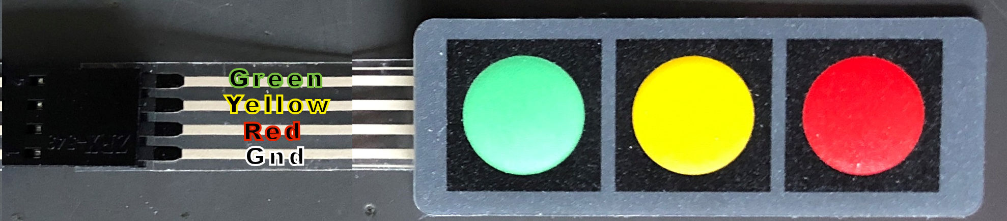
- four pins three button 3 x 1 keypad, to a one wire analogue output. |
|
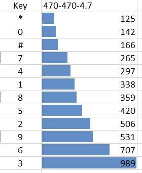
Three different resistor resistances are used.
This page:
http://www.circuitbasics.com/how-to-set-up-a-keypad-on-an-arduino/
explains nicely how the key
pad works.
There are many tutorials how to make a one-key wire keypad but or they use many
resistors, make use of libraries or are hard to follow.
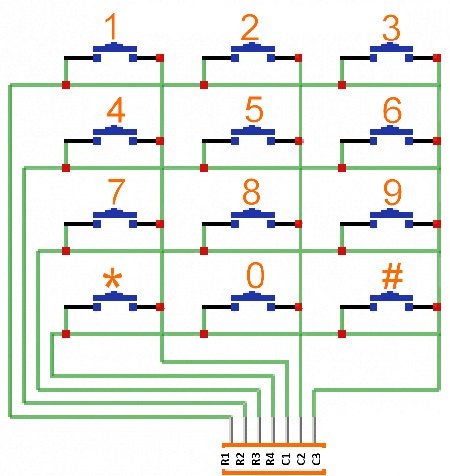
| In the picture on the right one can see that by
pressing a button a connection is made between a row and a column. By choosing the right resistor combination the output will be different for every button. 5V is connected to C1 and ground after a 1.1 kilo-ohm resistor. When 3 is pressed the current flows from R1 tot C3 and flows to a 1.1 kilo-ohm resistor resulting in a reading of 989 bits. Pressing * R4 and C1 and connected resulting in a flow through all the resistors and a reading of 125 bits. To discriminate between the buttons the difference between the difference button must be as large as possible. Because resistors of identical resistance value will not have exact the same resistance measured, readings between modules will vary a little. In the Arduino source code the range per button is large enough to overcome these differences. |
 |
 |
 |
 |
Source code OneWireKeyPad.ino |
OneWireKeyPad.fzz Fritzing file Below the source code to read the key values |
int sensorPin = A0;   // select the input pin for the potentiometer
int ledPin = 13;      // select the pin for the LED
int sensorValue = 0;  // variable to store the value coming from the sensor
byte keyvalue;

void setup()
{
 pinMode(ledPin, OUTPUT);   // declare the ledPin as an OUTPUT:
 Serial.begin(9600);
 Serial.println("Started. Press a key");
}

void loop()
{
 sensorValue = analogRead(sensorPin); // read the value from the sensor:
 digitalWrite(ledPin, HIGH);          // turn the ledPin on
 switch(sensorValue)
  {
    case   0 ... 100:  keyvalue = 13; break;   // noise
    case 101 ... 132:  keyvalue = 12; break;   // *
    case 133 ... 154:  keyvalue =  0; break;   // 0
    case 155 ... 216:  keyvalue = 11; break;   // #
    case 217 ... 281:  keyvalue =  7; break;   // 7
    case 282 ... 318:  keyvalue =  4; break;   // 4
    case 319 ... 349:  keyvalue =  1; break;   // 1
    case 350 ... 390:  keyvalue =  8; break;   // 8
    case 391 ... 463:  keyvalue =  5; break;   // 5
    case 464 ... 519:  keyvalue =  2; break;   // 2
    case 520 ... 619:  keyvalue =  9; break;   // 9
    case 620 ... 848:  keyvalue =  6; break;   // 6
    case 849 ... 1023: keyvalue =  3; break;   // 3
  }
 if(keyvalue<13) { Serial.println(keyvalue); delay(300); }
 digitalWrite(ledPin, LOW);   // turn the ledPin off:
}
I use this key pad instead of a rotary encoder.
Source code:
OneWireKeyPad3x1.ino
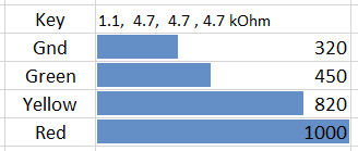
//--------------------------------------------
// KEYPAD check for Onewire Keypad input with 5V and 1.1, 4.7, 4.7, 4.7 kOhm resistors
//--------------------------------------------
int sensorPin = A0;   // select the input pin for the potentiometer
int ledPin = 13;      // select the pin for the LED
int sensorValue = 0;  // variable to store the value coming from the sensor
char keyvalue;
char Key;
void setup()
{
 pinMode(ledPin, OUTPUT);   // declare the ledPin as an OUTPUT:
 Serial.begin(9600);
 Serial.println("Started. Press a key");
}
void loop()
{
 sensorValue = analogRead(sensorPin); // read the value from the sensor:
 switch(sensorValue)
  {
    case   0 ... 385:  keyvalue = 99;            break;            // noise
    case 386 ... 635:  keyvalue = -1; Key = 'G'; break;            // G
    case 636 ... 910:  keyvalue =  0; Key = 'Y'; break;            // Y
    case 911 ... 1023: keyvalue =  1; Key = 'R'; break;            // R
  }
 if(keyvalue<2)
   {
    Serial.print(Key); Serial.print("  Read bits:"); Serial.println(sensorValue);
    digitalWrite(ledPin, HIGH);          // turn the ledPin on
    delay(300);
    digitalWrite(ledPin, LOW);           // turn the ledPin off:
   }
}
FibonacciClock
software V039 + libraries for one wire 4x3 keypad
November