<-- Home
Testing optocouplers and a level-shifter with the ESP32 and RGBW SK6812 LED-strip.
And why level-shifters are not needed with the SK6812 RGBW LED-strip.
Conclusion:
Connect the SK6812 RGBW strip directly to the ESP32 output pin of use a quad
level-shifter 74AHCT125
If you have a brilliant idea then test it.
In many projects with Arduino MCU's like the UNO, Nano and Every I use SK6812
RGBW LED strips. Experiments with the RP2030, MKR and 33 BLE were problematic
when using WIFI and BLE simultaneously.
With the arrival of the ESP32 Nano in 2023 I decided to concentrate on this this
platform. Experiments with the ESP32-C3 and S3 convinced me to use the ESP32
Nano when it came on the market.
The Arduino ESP32 Nano is in fact an Espressif ESP32-S3 chip used on a Arduino
Nano board.
ESP32 boards are a nightmare to use. The are far too many variants in sizes and the use of pin numbers. A designed circuit board (PCB) for a particular ESP32 board is soon outdated. So I will stick to the Arduino-family. The Arduino Nano ESP32 has designed a reliable 5V 3V3 separation. The USB, used for power and uploading is still 5V. It still has a 5V pin but this is only powered when a USB-C cable is connected. To power the MCU the Vin pin can be connected to a 5V – 18V power supply.
But …
The SK6812 RGBW strip has a 5V data line and needs 5V power voltage. The ESP32
only delivers 3.3V on its output pins
But we have to deal with an MCU operating at 3.3V and 5V sensors and in this
case LED-strips.
My idea was to use the optocoupler. I like the idea of the two independed
power sources. Especially with the LED-strips that can consume a lot of current.
It keeps the 5V also save away from the MCU.
The signal send to the LED strip is around 800 kHz. The Arduino Nano is able to
generate such frequencies when assembler is used.
When looking at the optocoupler 4N25 / 4N35 datasheet one can find a turn on and
turn off period of 3-10 us.
That is 1,000,000 us / 5 us = 200.000 Hz = 200 kHz
Worth trying.
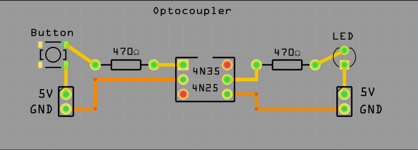
A simple start with a button.
It works. When the button is pressed the LED lights up.
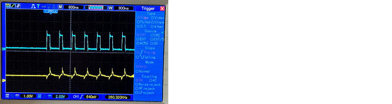
Let try to see how it performs when we put a square wave signal on it
But when hooking up the oscilloscope the signal from the optocoupler is reversed!
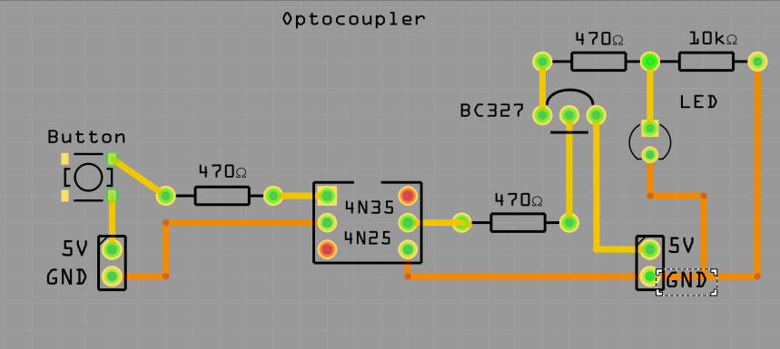
The Max Frequency of a BC327 is 100MHz. That must be no problem but we need
extra components.
But in the end the LED-strip did not light up.
After searching on the internet I found the 6N137 was a much faster optocoupler.
The data sheet mentions an Output Rise/Fall time of 30 ns (33 MHz). That is
33,000,000 Hz. About 40 times more than needed.
The result with the 6N137 optocoupler was also negative.
Measuring the output signal in the oscilloscope were also not promising.
I tried with some capacitors of different capacities of the output but the
signal remained too bad..
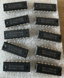
In my opinion these results were far beyond repair and I moved at last to the
4-channel quad level-shifter 74AHCT125.
For my projects at the moment too many ports but I could connect some of the ESP32 ports on my PCB optionally via the level shifter. Then my PCB was also more future proof.
The level shifter in a test setup worked flawless.
I ordered the redesigned PCB board suited for a ESP32 Nano and the RGB(w) LEd
strips
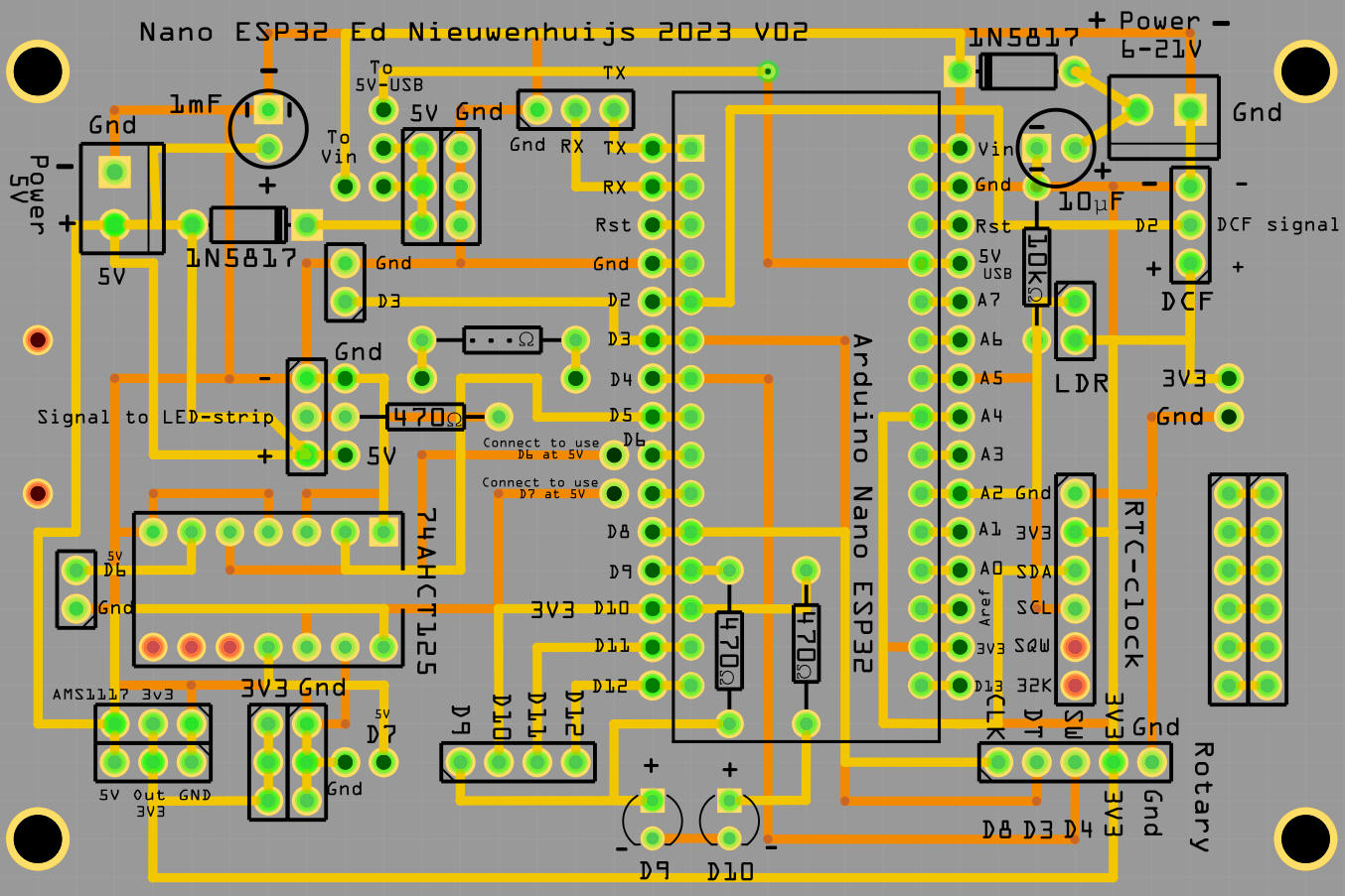
The PCB with the quad level shifter to be
used with a Arduino Nano ESP32.
The LED strip is connected from D5. The board is powered via Vin when the 5V pin
after the 1N5817 is connected to the "To Vin" pin
Powering to 5VUSB does not work
a DS3231 module is connected to RTC-clock en a LDR to the LDR pin. Power 6-21V
is optional
A rotary can be connected to the rotary connector at the bottom
The PCB can also be used with a DCF77-receiver. the 1N5817 diodes are optional
and for protection. But if you do not want the voltage drop replace the with a
wire.
D6 and D7 can be used with the level shifter.
Source code for the clock here:
https://github.com/ednieuw/Arduino-ESP32-Nano-Wordclock
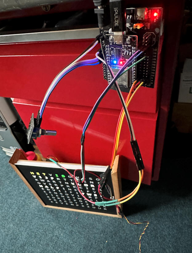
My last thought was: “What the hack. Let’s connect a 96 LEDs long SK6812 RGBW strip data line directly without a 470 ohm resistor (where is this needed for?), to an ESP32.
And wonder. It also works.
When the first LED manages to get started the signal in the data line is
probably shifted up to 5V by this first LED because the power is 5V on VCC and
GND.
The Hackaday “Cheating-at-5v-ws2812-control-to-use-a-3-3v-data-line”trick is
probably not needed with a SK6812.
The test with an ESP32 and a word clock with 96 LEDs SK6812 LEDs works now flawless for two weeks.
Fritzing file Nano_ESP32-PCB_V02
<-- Home
Ed Nieuwenhuys january 2024