Building instructions SK6812 color word clock
Translated from
Dutch with Google translate
This word clock uses SK6812 RGBW to illuminate the text of the clock in a
color.
The letters of the word plate form the illuminated words that indicate
the time.
This word clock with an ESP32 is described here on Github
.
RGBW LED strips have a white LED built in in addition to the RedGreenBlue
LED.
This makes it possible to see bright white words in addition to colored
letters.
The software for this clock has the option to use WS2812 RGB LEDs.
With RGB LEDs, white has a slight color cast.
The LEDs each contain a small processor so that the entire chain of LEDs
can be controlled with one wire.
The software for this clock is designed for 12 x 12 LEDs in a 25 or 50 cm
case.
LED strips are available with 30 or 60 LEDs per meter so that there is
exactly one LED behind each letter and the strip does not have to be cut
up.
This makes construction easier and offers the possibility for a digital
clock display.
The white LED clock
is also worth considering.
The software source contains code for multiple options in the execution
of the clock.
With #defines in the software, the various options are switched on or
off.
The first three modules are required in any case to use the clock
- RTC DS3231 ZS-042 clock module
- KY-040 Keyes Rotary Encoder
- LDR light sensor GL5528
Particularly recommended is - Bluetooth to
control
the clock with IOS BLE Serial Pro
or Android app. Additional code for:
- DCF77 module DCF-2
- LCD
- WIFI on MKR 1010 NTP time
- HC12 transceiver
- 3x4 or 3x1 membrane keyboard
- Four languages
; Dutch, German, French and English
- A manual
- Possible support via email.
The manual
describes in detail the operation of the clock
- with the rotary knob
- or controlled via the menu with the Bluetooth apps for IOS and Android
- or control with a connected PC. |
.JPG) 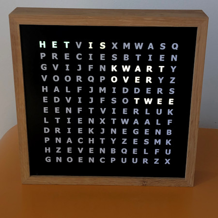 Colors are much more colorful in reality than in the photo.
|

The word clock consists of the components as shown in the table below.
In addition, the software offers the option to use an ATMEGA 1284 processor.
I have printed circuit boards for this
.
The word clock components are designed for 25x25cm and 50x50cm word plates.
The center distance between the letters is 1.67 or 3.33 cm. The LED strips
have 30 or 60 LEDs per meter on a strip.
The 25cm clock has 60 LEDs per meter strips and the 50cm clock 30
LEDs/meter.
The table shows the prices for which you can order the components, if still
in stock, from me as a self-assembly kit.
The word plate is handmade by a letterer.
The construction time of a clock is 20 - 30 hours.
Supplies
Soldering Supplies
Multimeter
Excel sheet with components
Assembling the lighting base plate
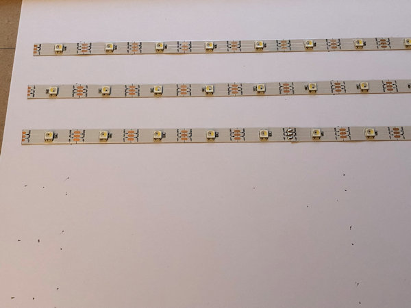
The distance between the LEDs on the strip is suitable for making a clock of
25 x 25 cm (60 LEDs/m) or 50 x 50 cm (30 LEDs/m).
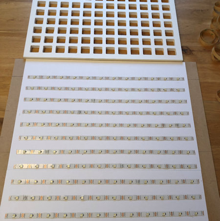
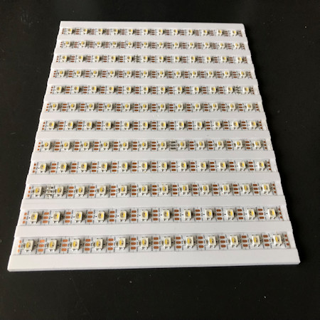
You can choose to stick the 144 LEDs of the clock in 12 rows of 12 LEDs or
only behind the letter that should light up.
The latter has the advantage that fewer LEDs are needed and that you have
to drill fewer holes in the spacer plate.
There are then many more solder points that can each cause interference.
My experience is that imperfect soldering on the strip sometimes comes
loose over time.
The software also has a digital time display that you cannot use if you do
not install all 144 LEDs.
You can also choose to saw out the illuminated words in a 1 cm thick MDF
board with a jigsaw.
Then paint the insides bright white, otherwise the white light will become
dirty.
Paste the strips from left to right on the odd lines and from right to left on
the even lines. Follow the arrows on the strip
.
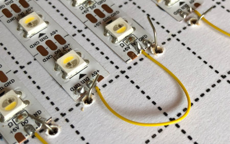 |
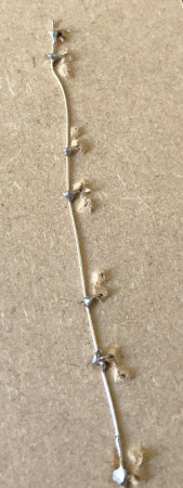
I find it useful to use tinned copper wire. For example, you solder all 5V
connections on the left side of the strip and all GND on the right side of
the strip.
Drill a small hole through the plate next to all 5V connections on the
left side of the strip and to the GND on the right side.
Bend a 90 degree angle, put the wire through the hole and solder the wire
to the LED strip. |
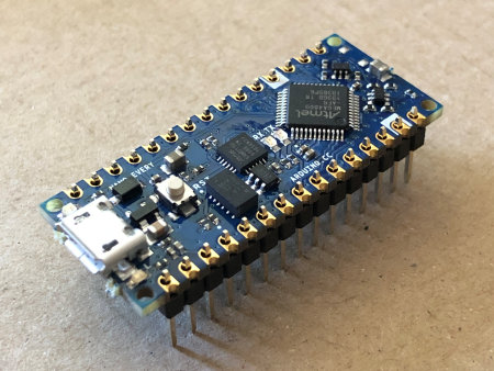 |
Solder the legs of the Nano Every so that the long legs are at the bottom
when the chip and USB port are at the top.
The numbers and text on the Nano should then match the numbers on the PCB. |
|
| |
|
Apply solder to the LED strip connection and later solder the wire into the
solder blob.
At full load, a fair amount of current (1A) will flow. If you connect all the
strips one after the other, a lot of current will flow to the first LEDs and
the wire must be thick.
I make a connection per two lines from the power wire with 30AWG = 0.25mm
diameter. 30AWG wire can handle 0.9 A current
or uninsulated tinned copper wire of 0.6mm on one side of the strips the 5V
connection and on the other side the ground connection.
Finally, make sure that each strip has its power supply.
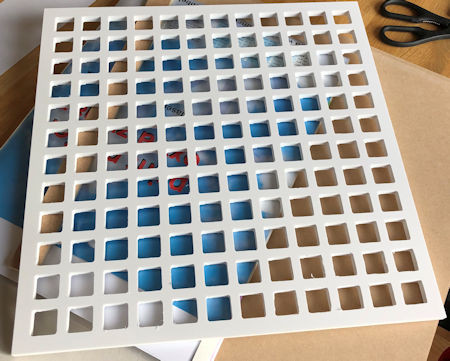
On the front, on the LEDs, the spacer plate will be placed and this must lie
flat on the surface to prevent light leakage.
 |
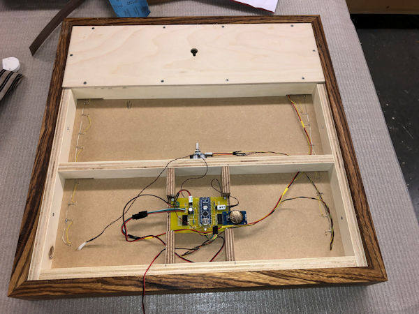 |
| Front |
Back after wiring |
In the signal wire between LED_PIN 5 (D5) of the Arduino and the SK6812 LED
connection Di there is a 470 Ohm resistor.
Across the GND and 5V to the LED strip there is a 1 mF (1000 uF) capacitor to
dampen the switch-on voltage.
The LEDs do work without these two components but can be damaged when the
power is turned on.
You can also connect all components directly to the pins of the Arduino Nano
without the printed circuit board.
There is a PCB where everything can be soldered. This printed circuit board
can also be used for the Fibonacci clock
.
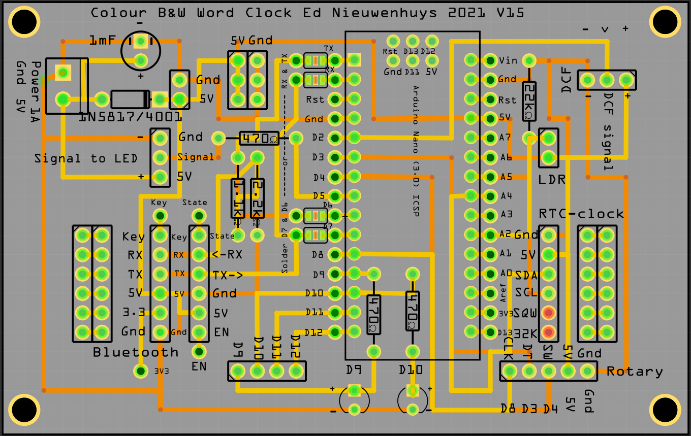
The latest PCB version V15
has fixed connections for the most commonly used components.
It is now possible to choose whether the serial connection to the Bluetooth
module goes via the standard connections 0 and 1, TX and RX, or whether it
goes via connections D6 and D7. An additional library is then used in the
software that takes up additional program space.
The advantage is that you can load the program into the Arduino without
having to disconnect the Bluetooth module. This interferes with the upload of
the program.
In the current software version, D6 and D7 are used for the Bluetooth module
and the pads at D6 and D7 must be soldered shut.
In PCB V15 a diode 1N5817 or 1N4001 is added to prevent that when connecting a
long LED strip too much current is supplied via the USB port of the Arduino
Nano and connected PC.
Up to 30 LEDs, and possibly 100 LEDs, can be supplied by the USB port and the
diode can be replaced by a wire.
But there is a limitation and if the current demand is too high the Arduino
will be damaged
 |
|
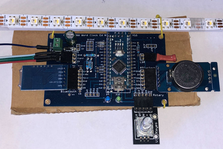
The parts in place. In this example pin 0 & 1 (Tx&RX) are connected to
the Bluetooth
|
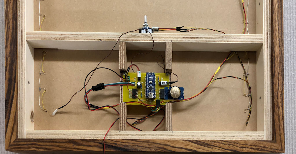 |
| The connections in the cabinet |
|
Below is a list of the connections on the Arduino
// digital port connections D2 - D13
DCF_PIN = 2, // DCFPulse on interrupt pin connected to DCF77 module
encoderPinA = 3, // Rotary right (labeled DT on decoder)on interrupt pin
clearButton = 4, // Rotary switch (labeled SW on decoder)
LED_PIN = 5, // Pin to control color 2811/2812 leds
BT_RX = 6, // Bluetooth RX, Connect to Bluetooth TX
BT_TX = 7, // Bluetooth TX, Connect to Bluetooth RX
encoderPinB = 8, // Rotary left (labeled CLK on decoder)no interrupt pin
EmptyD09 = 9, // EmptyD09
DCF_LED_Pin = 10, // pin for LED to display pulse received from DCF77 module
PWMpin = 11, // pin for LED to display intensity read from LDR
EmptyD10 = 10 , // EmptyD10
EmptyD11 = 11, // EmptyD11
EmptyD12 = 12, // EmptyD12
secondsPin = 13,
// digital port connections A0 -A5
PhotoCellPin = 2, // LDR pin
EmptyA3 = 3, // EmptyA3
SDA_pin = 4, // SDA pin of the DS3231 clock
SCL_pin = 5}; // SCL pin of the DS3231 clock
Assembling the clock
It is useful to tape the parts of the clock together with paper masking tape.
This tape comes off easily.
Tape the illuminated plate and spacer together.
Tape a white sheet of paper over the spacer. Paper gives a nice drawing to
the illuminated letters.
Place the word plate over the paper and fix it with tape as well.
With a hardwood clock, depending on the version, the word plate is slid into
the slot in the case.
Then mount the fourth, bottom side of the case.
Glue this or temporarily tape it with a tape machine.
When everything is properly labeled, the clock, rotary encoder, LDR, power
supply can be connected.
Assemble the case.
Bluetooth connection
With an HC05 or HM-10 or JDY-23 Bluetooth module, a Bluetooth connection can
be made with the clock.
The HC05 only communicates with Android. The HM-10 and JDY-23 communicate
with both Android and Apple iOS.
The link below describes which pins the module is connected to and how the
name of the module is adjusted.
With a Bluetooth terminal app
on the phone, the time can be sent to the clock as hhmmss or hhmm.
The clock sends data back to the terminal app every minute.
Bluetooth terminal apps can be found for Windows phone, Android and Iphone.
The Bluetooth terminal programs can also be found for PCs.
The Bluetooth module communicates between RX (read) and TX (transmit) with
3.3V.
It is possible to connect it directly to the Arduino ports, but it extends
the life of the module if the voltage is lowered to 3.3V.
This can be done with a 3.3V-5V TTL Level Logic Level Converter module, or
with a “voltage divider†circuit with resistors as shown below.
You can also mount the resistors in the wiring from the module to the
printed circuit board.

Bluetooth with the HM10 BLE for Apple IOS
With this HM10 BLE module you can communicate with Apple IOS and Android.
Then you can send commands with a serial terminal program
( BLEserial HM-10 for IOS
or
for Android BLE scanner from Blue Pixel Technologies) and capture the clock output.
Connected via an FTDI, AT commands can be given with the Arduino serial
monitor with the Bluetooth module.
See previous paragraph for AT commands
AT+NAMEnewname gives the module the name: newname
More info about Bluetooth communication here.

DCF77 reception with DCF-2 module

Unfortunately, the ICs in the color LEDs interfere with DCF reception.
With these color LEDs, the DCF reception module must be hung at least 10 cm
or more from the LEDs and a good interference-free power supply is essential.
With an LED on the PCB or with serial communication, reception can be
followed.
This DCF77 module has three connections; +, - and signal.
Connect the + to 5V and the - to GND.
Signal goes to pin 2.
NB Pin 2 was used for the rotary encoderPinB left (labeled CLK on decoder).
This is now connected to P8. (Pin 2 is an interrupt pin. For optimal DCF
reception, responding to an interrupt is not
necessary
for the rotary encoder .
Look in the source of the version of the software under "PIN assignments"
for the correct connection. Background information about DCF here.
Clock power consumption
The clock consumes 0.15A at 5V when the LEDs are on at half strength.
When all LEDs are on, the consumption is 0.6A.
For normal use, a power supply of 5V 1A is sufficient.
Source code
This
Github link
also contains this and newer versions. Character_Colour_Clock_V076 Manual SK6812-WS2812-wordclock V076.pdf
This is a stable version that has been running in clocks for over a year
Latest version V087
+ required libraries: Character_Colour_Clock_V087.zip
Manual SK6812-WS2812-word clock V087.pdf
The zip file contains two INO files V087 and V087tiny
V087 also contains the code for the 4-language clock, is very extensive and
supports various displays and input methods.
V087tiny only contains code for the Dutch word plate with a rotary knob and
Bluetooth.
This version is sufficient for most applications.
Software on Github
Software
The used libraries must be installed and can all be found in the Arduino IDE.
To be sure, the used libraries are packed in a ZIP file
#include "RTClib.h" // https://github.com/adafruit/RTClib
#include <TimeLib.h> // For time management
#include <Adafruit_NeoPixel.h> // https://github.com/adafruit/Adafruit_NeoPixel
#include <SoftwareSerial.h> // For Bluetooth
#include <Encoder.h> // http://www.pjrc.com/teensy/td_libs_Encoder.html
#include "DCF77.h" // http://playground.arduino.cc/Code/DCF77
At the top of the source, #defines indicates which code for the Arduino Nano
Every should be compiled.
With // before a #define you turn off the source code for that part.
For example:
//------------------------------------------------ ------------------------------
// Definition of installed modules
//------------------------------------------------ ------------------------------

// ------------------> Define only one library
#define NEOPIXEL // Adafruit Neopixel for WS2812 or SK6812 LEDs
//#define LIBSK6812 // SK6812 library. Only with SK6812 LEDs (saves 614 bytes with NEOPIXEL)

// ------------------> Define which module is present.
#define BLUETOOTHMOD // Use this define if Bluetooth needs other pins than pin 0 and pin 1.
                                //#define BLEnRF52MOD // turn on for RP2040, Nano BLE33 , MKR1010 etc
#define MOD_DS3231 // The DS3231 module is installed, if not the Arduino internal clock is used
                                //#define LCDMOD // For LCD support
#define ROTARYMOD // Rotary encoder installed
In this example, the Adafruit Neopixel library is used and the LIBSK6812
library is not.
#define NEOPIXEL
//#define LIBSK6812
Next example:
#define BLUETOOTHMOD // Use this define if Bluetooth needs other pins than pin
0 and pin 1.
//#define BLEnRF52MOD
We use the Bluetooth module but it is not connected to pin 0 and 1 but to
pin 6&7.
To save pin 6&7 the Bluetooth module can also be connected to the serial
port pins 0 and 1.
But if a program is uploaded to the Nano Every the Bluetooth module must be disconnected!
The program is then also sent to the Bluetooth module which will protest
violently.
Look further in the program how pin 6&7 are used with the library
Softwareserial.
In the source code you will find code between #ifdef and #endif.
This code is then only compiled if that part is defined with a #define.
Using these definitions saves program space but also unnecessary commands
from a module that is not present but is read by the software on unconnected
pins. That can only become a nuisance.
If you run out of space you can use my library SK6812. That library uses a
little less memory.
NL144NL is to select the 144 LED display with Dutch text. FOURLANGUAGECLOCK is
to make a four-language clock.
The other defines are to select the various modules.
MOD_DS3231 is the time module.
To test it can be useful to turn this off. Then the internal Arduino clock is
used.
This is much more inaccurate and deviates seconds per hour while the DS3231
deviates a maximum of 5 seconds per million seconds.
So if the clock is not running smoothly, check whether the correct option has
been selected.
For example:
        #ifdef MOD_DS3231
RTC_DS3231 RTC clock;
        #else
RTC_Millis RTC clock;
        #endif
There are DS3231 modules in circulation that deviate greatly. Then you will
have to replace them.
The DCF77 receiver is for the hobbyist. Sometimes it is not possible to
receive the time for days.
This can be due to a bad power supply to the clock or to the same socket.
Sometimes the neighbours have an interference source but also the colour LEDs
in the clock interfere.
Sometimes it is just bad reception conditions.
That is why I made a large DCF receiver
and a small one
, which I know works.
If my new design does not work next to this receiver either, I know that it is
probably due to the software.
The receiver must in any case be at least 15 cm from the clock with the
ferrite rod approximately North-South oriented
So perpendicular to the transmitter in Germany. The yellow LED must flash
regularly.
The signal can be examined with the menu option A.
More DCFNanoEvery/DCFHC12Transmitter
and here DCF77_transceiver/DCFtransceiverklok
.
// ================================================= ==================================================== ============================================
// //
//------------------------------------------------ ------------------------------
// ARDUINO Definition of installed modules
//------------------------------------------------ ------------------------------
// ------------------> Define only one type of LED strip
                                //#define LED2812
#define LED6812 // Choose between LED type RGB=LED2812 or RGBW=LED6812
// ------------------> Define only one library
#define NEOPIXEL // Adafruit Neopixel for WS2812 or SK6812 LEDs
                                //#define LIBSK6812 // SK6812 library. Only with SK6812 LEDs (saves 614 bytes with NEOPIXEL)

                                //#define FOURLANGUAGECLOCK // Selectt this define for the 4-language clock with 625 LEDs
#define NL144CLOCK // Or select this define for the Dutch clock with 144 LEDs4

// ------------------> Define which module is present.
#define BLUETOOTHMOD // Use this define if Bluetooth needs other pins than pin 0 and pin 1.
                                //#define BLEnRF52MOD // turn on for RP2040, Nano BLE33 , MKR1010 etc

                                //#define WIFIMOD // When WIFI module is available

                                //#define HC12MOD // Use HC12 time transreceiver Long Range Wireless Communication Module in Bluetooth slot
#define DCF77MOD // DCF77 receiver installed
#define MOD_DS3231 // The DS3231 module is installed, if not the Arduino internal clock is used
                                //#define LCDMOD // For LCD support
                                //#define HT16K33time // 4-digit HT16K33 time display installed https://www.adafruit.com/product/879 Adafruit GFX library

#define ROTARYMOD // Rotary encoder installed
                                //#define KEYPAD3x4 // Use a 3x4 keypad with 7 wires
                                //#define KEYPAD3x1 // Use a 3x1 keypad with 4 wires
                                //#define ONEWIREKEYPAD3x1 // Use a 3x1 keypad with one wire
                                //#define ONEWIREKEYPAD3x4 // Use a 3x4 keypad with one wire
#define HET ColorLeds("Het", 0, 2, MINColor);
#define IS ColorLeds("is", 4, 5, SECColor); ColorLeds("", 8,10, 0); Is = true;
#define WAS ColorLeds("was", 8, 10, SECColor); ColorLeds("", 4, 5, 0); Is = false;
#define EXACTLY ColorLeds("exactly", 17, 23, LetterColor);
#define MTIEN ColorLeds("ten", 12, 15, LetterColor);
With #define it is also possible to combine multiple commands into a text.
What is important in the above #define is the function ColorLeds().
This indicates which LEDs should light up for a word.
The first LED has number 0 (zero)
WAS is lit by LEDs 8, 9 and 10.
The numbering can be adjusted if the design has changed slightly.
For example, if you forgot to change the direction of the LEDs every line
when sticking them on. (-:
After all the initializations used
between #ifdef and #endif
the Setup() function follows.
In this the selected modules are started.
The setup() is run once at the start of the Arduino.
Then the program goes to the loop() function.
The program keeps walking around here and we only get out with the functions
that are called in it.
In this program:
Void loop()
{
                      InputDevicesCheck();
 if (Demo) Demomode();
 else if (Selftest) Selftest();
 else EverySecondCheck();
}
InputDevicesCheck() checks if there is input of something and processes that.
For example SerialCheck(); RotaryEncoderCheck() and BluetoothCheck();
Furthermore, the EverySecondCheck(); is important. All sorts of things
happen there that have to happen within a second.
Then follow EveryMinuteUpdate, EveryHourUpdate, EveryDayUpdate.
Personally, I think this is a nice method to not waste unnecessary time on
functions.
For example, dimming the display when you hold a finger in front of the LDR
can be checked once per second.
The time only has to be changed once per minute. Et cetera
Input from the serial port or Bluetooth is processed in ReworkInputString();
These were the basics of the program flow.
If you have any further questions, you can email me.
<- Back to homepage
Order list in Excel
This word clock using an ESP32 is described here on Github
.
E-mail
Ed Nieuwenhuys. August 22, 2024
April 16, 2023,
Oct 18, 2022, May 27, 2021, March 18, 2021, Nov 13, 2020, August 5, 2020,
December 23, 2019
Below the older PCB version 08.
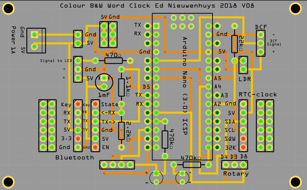
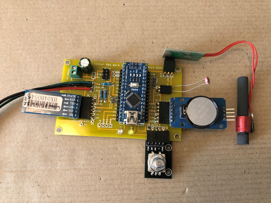
<- Home page
Old
Arduino Nano Every with SK6812 or WS2812 LEDs
Manual SK6812-WS2812-wordclock V069V070.docx
WordclockSK6812_files/Character_Colour_Clock_V070.zip
For 144 LEDs with Arduino Nano Every
Since 2020 the Arduino Nano Every with 48Kb memory instead of 32Kb can be
purchased officially very cheaply
. In this version a DCF77 receiver can be used.
There are also options available to work with the MKR1010 with WIFI or to
compile for the ATMEGA 1280/1284 chips.
Version for Arduino Nano Every with 144 LEDS.
Character_Colour_Clock_SK6812_1284-V036-Nano-144_LEDs.ino
For up to 96 LEDs with Arduino Nano or Arduino mini
The source code to control the clock can be used for the Arduino Nano Uno and
mini up to version V076.
Then a clock with a maximum of 96 LEDs must be made.
That is 1 LED under each letter that is used to display the time.
Keep the
program size under 23572 bytes
!
The LED libraries uses memory that is not written off. If the program becomes
too large, for example, the serial and/or bluetooth communication will
suddenly stop.

