<--
Home
-> Dutch instructions
This square case clock is a variation on the
Fibonacci clock. The software is simplified and suitable for two types of color LEDs.
The Fibonacci clock was a kick-starter project by
Philippe Chrétien .
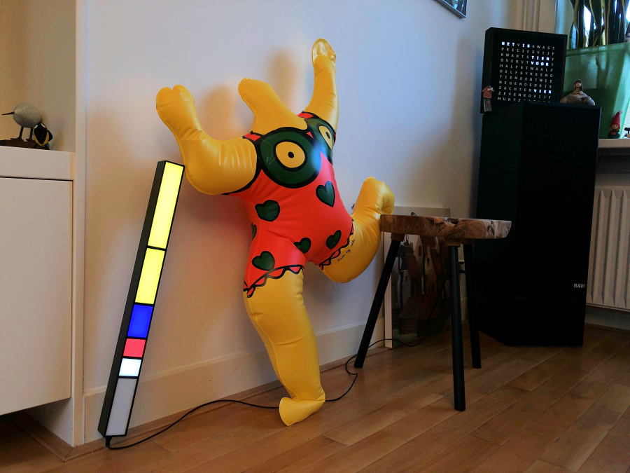
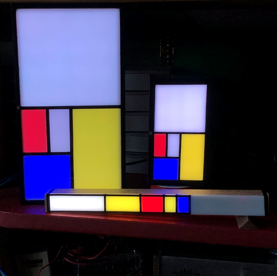
What makes this clock so attractive is its simplicity, ingenuity and the constantly changing Mondrian-like painting display.
Mondriaan was also looking for simplicity in his paintings, which started with realism and ended with his characteristic style via cubism.
In addition to the play of colors, this clock invites you to recalculate the time presented.
But a clock? And what does Fibonacci have to do with Mondrian?
The colored areas separated by black lines are immediately reminiscent of Piet Mondriaan 's paintings when the primary colors red, yellow and blue are used.
This clock uses colors and surfaces that follow the Fibonacci sequence .
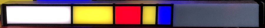
Red + Blue = hours, (Yellow + Blue) x 5 = minutes.
The stick above has 1 red + 2 blue areas = 3 hours.
In addition, 3 + 5 = 8 yellow areas + 2 blue areas = 8 + 2 = 10 areas of 5 minutes = 10 x 5 = 50 minutes.
1 + 2 = 3 hours, (8 + 2) x 5 = 50 minutes It is 3:50, ten to four.
| What the clock does is turn on the lighting behind the areas that are to be added. A third color, blue, is used to combine the hours and minutes. The red areas are the hours. The yellow areas multiplied by 5 are the minutes and the blue areas when a red and yellow occupy the same area. The white areas mean zero, they mean nothing with addition. Fibonacci was an Italian mathematician who developed the series of numbers named after him. It was not a normal series of numbers, but one that also often occurs in natural processes. For example in sunflowers and shells. The sequence is simple. Each next number in the series is the sum of the two previous ones: 1, 1, 2, 3, 5, 8, .... If we add 1, 1, 2, 3, 5 we get 12. Ah, exactly the number of hours in a half day and 12 multiplied by 5 is the number of minutes in an hour. Example: 4 hours. This can be a sum of: 1+1+2 or 1+3. Example: 8 hours. This can be achieved by adding 1+1+2+4, or 1+3+4 or 3+5. The clock's display is a representation of the Fibonacci sequence and the area of the faces is the ratio of the area in the sequence. |
 |
|
The construction of the cabinet The cabinet can be made by hand or printed with a 3D printer. The minimum space required to build the electronics in a cabinet is 25 x 25 x 100 mm internal dimensions if an Arduino Nano is used with the connection pins on one side. |
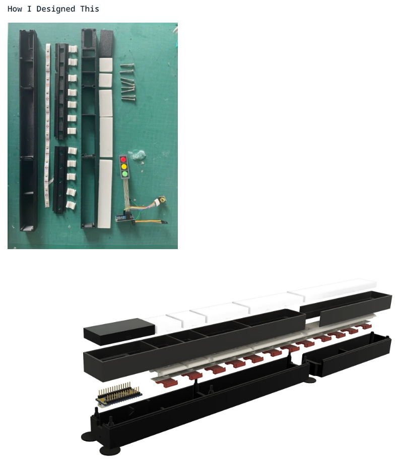 |
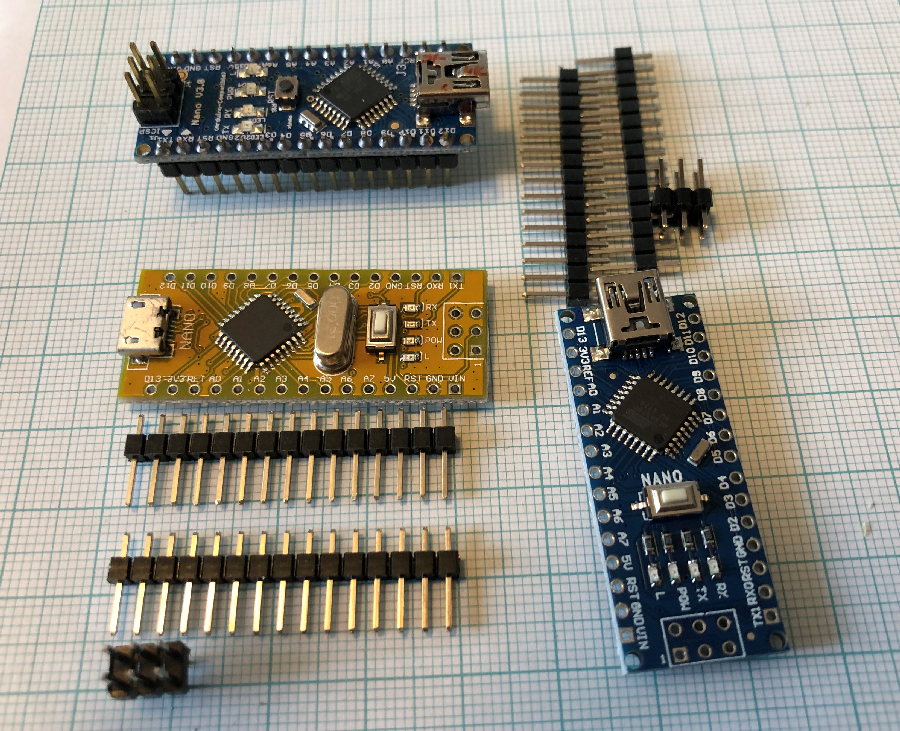
The Nano Every, released at the end of 2019, no longer has the six pins, which makes it lower (and also cheaper).
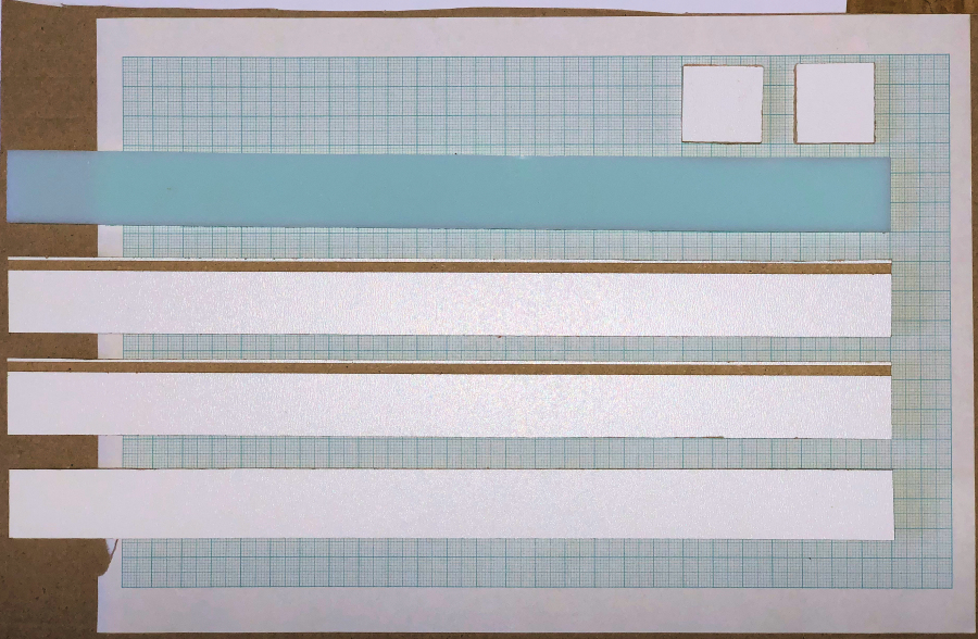
The inside of the compartments where the lighting is on must be perfectly white.
For example, you can use white MDF for this.
But it can also be easily stuck by white paper to the inside of the compartments.
Thin, sturdy cardboard, MDF or other material can be used as a separation between the compartments. Do not make it thicker than 2 mm.
It is nice when the white perspex top plate falls into the wood.
To do this, use a saw table to cut a slot 1 mm deep in the side, 1-2 mm below the top at the thickness of the perspex sheet.
But of course it can also be stuck between the sides.
For the smallest cabinet with an LED strip of 60 LEDs per meter:
- Saw a strip for the bottom 25 mm wide and 300 mm long.
- Immediately saw a strip of 25 mm wide (maximum 2 mm thick) for the partitions for the compartments and saw the seven partitions to size (25x25mm).
If the compartment dividers are cut from cardboard, this can be done later.
- Saw two sides of 35 cm to a width of 25 mm + the thickness of the bottom plate.
- If necessary, saw out a slot just below the top edge into which the perspex can fall.
- Cut out the sides of the end edge with a width of 25 mm.
- Stick white paper on all partitions and sides of the cabinet where the lighting will be located.
- Glue the cabinet together except for one end edge. Useful! Use paper masking tape to keep the parts firmly clamped together.
- Stick the LED strip to the bottom from the glued end edge.
- Apply a drop of Bison sealant to the sides of the strip to prevent the side of the strip from curling up over the years.
- Install the electronics (see below) and glue the dividers in place.
- Finish the cabinet neatly if the electronics work properly.
- Tape the compartment divisions on the perspex with 2 mm wide black adhesive tape or draw the compartment divisions on the perspex with a black felt-tip pen for a better contrast between the light surfaces.
For the large 52 cm cabinet with an LED strip of 30 LEDs per meter:
The advantage of the larger cabinet is that a larger and more accurate DS3231 time module can be used.
The dimensions are then 40 x 40 mm per compartment and the length of the cabinet is 520 mm.
The LED strip then contains 30 LEDs per meter.
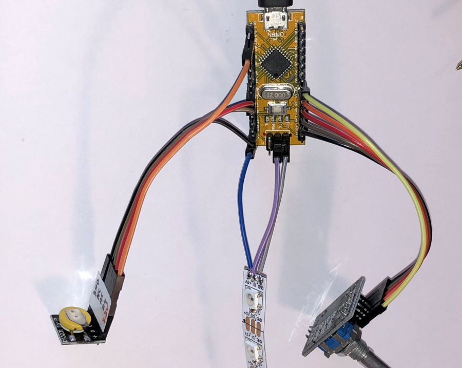
Assembling the electronics
The requirements for the electronics are shown below.
A soldering iron is needed to solder three wires to the LED strip.
The light-sensitive sensor and the resistor should preferably also be soldered.
A multimeter costing 10 euros is useful to measure the resistances and check any bad connections.
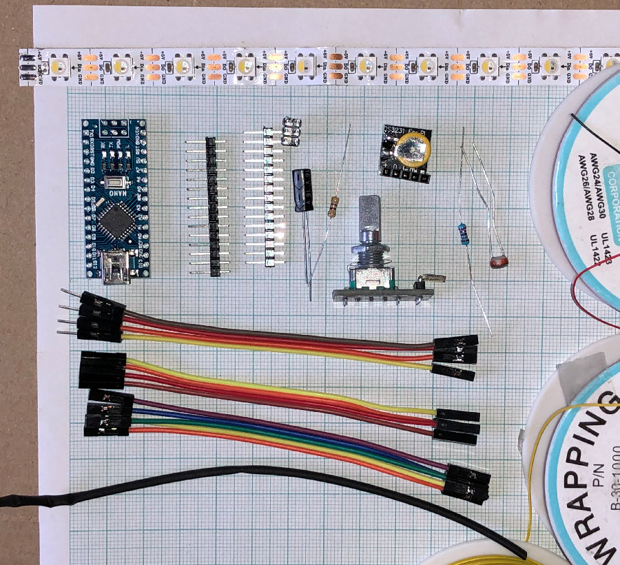
Required:
- WS2812 of SK6812 LED-strip met twaalf LEDs
- Arduino Nano of
Arduino Nano Every
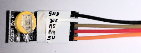
- DS3231 RTC-module.(1) DS3231 for Pi of DS3231 RTC
- 100 - 1000 uF condensator
- 330 of 470 ohm weerstand
- 22 Kohm weerstand
- LDR (lichtgevoelige weerstand)
- Rotary encoder
- 9 Dupont-kabeltjes vrouw-vrouw
- 4 Dupont-kabeltjes man-vrouw
- Isolatieband of krimpkous met diameter van ongeveer 2 mm
- Een paar stukjes draad
- Soldeerbout en soldeer
(1) In de kleinste klok past alleen de "DS3231
for Pi" klokmodule.
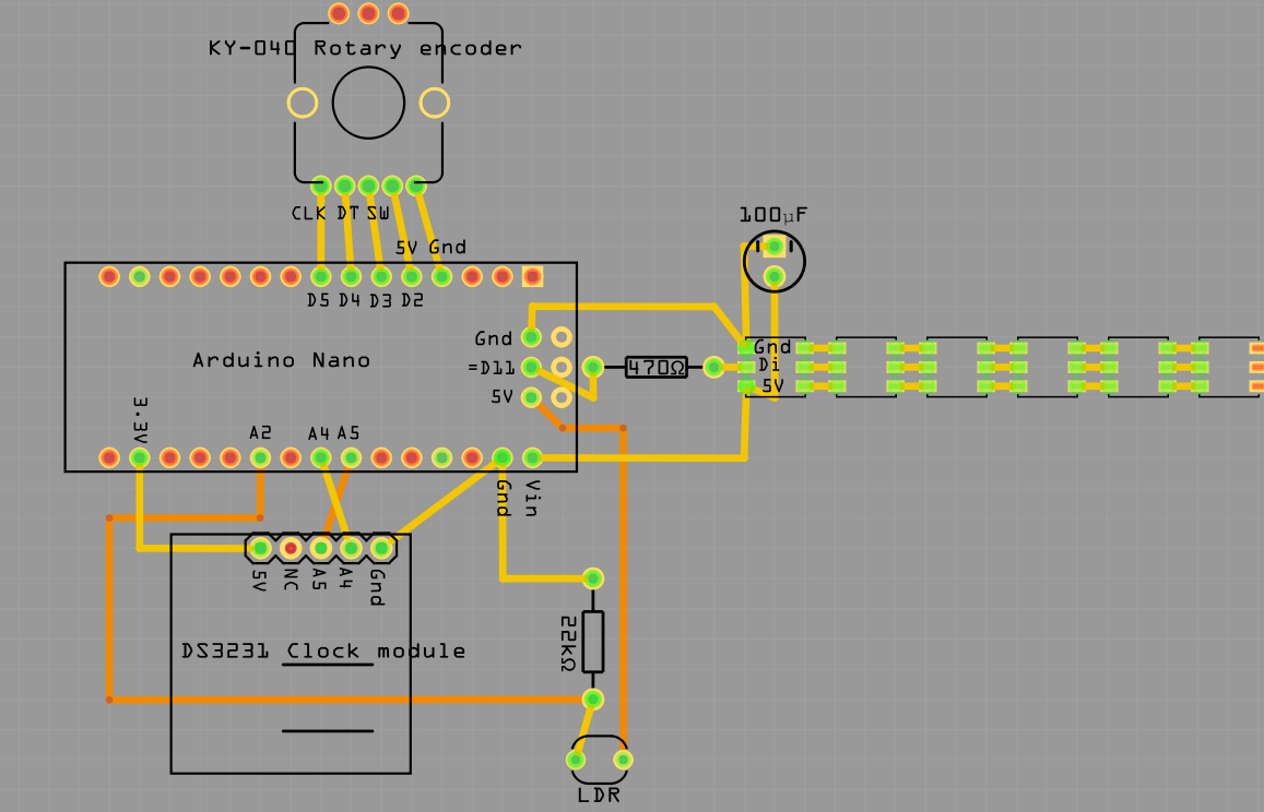
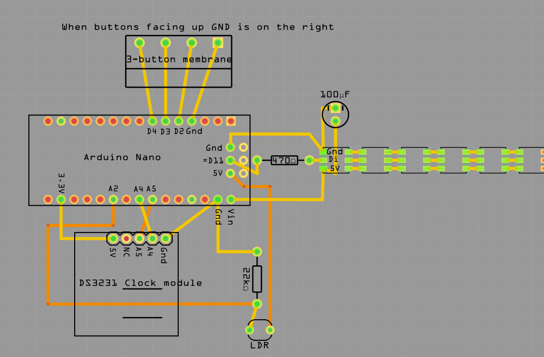
Hieronder is het aansluitschema getekend.
Bij Fritzing kan het programma
gedownload worden om deze schema's te ontwerpen
Click op het plaatje voor het ontwerpbestand dat in het Fritzing-programma kan
worden ingelezen en bewerkt.
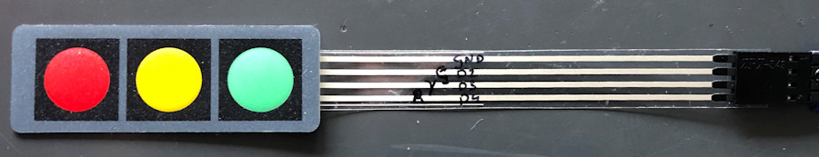
In software versie V023 kan ook een platte 3-knops membraan gebruikt worden
in plaats van de rotary.
Als de membraanknoppen zichtbaar zijn en horizontaal
ligt dan is GND de bovenste draad.
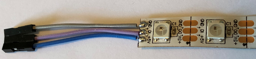
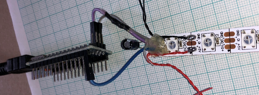
Solderen van de LEDs
- Breng soldeer aan op de drie aansluitingen aan de LED-zijde waar de GND-aansluiting boven ligt.
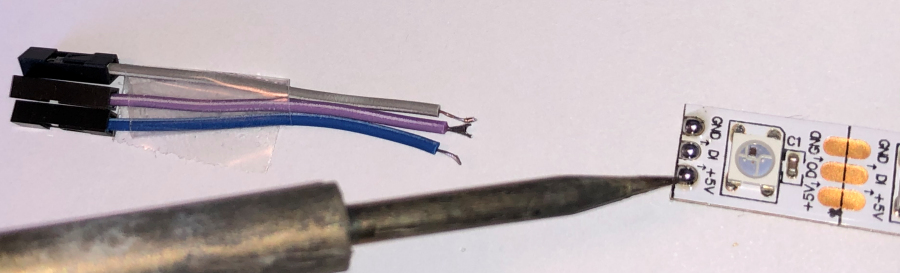
- Soldeer de drie Dupont-draden van ongeveer 5 cm lengte vast.
De weerstand is een extra beveiliging en kan eventueel
weggelaten worden.
- Knip de middelste draad, verbonden met Di, door en soldeer hier de 470 ohm
weerstand tussen.
Di is "Data in" en Do aan de andere kant
van de LED is "Data
out".
Dit is dus de signaaldraad die aan de LEDS doorgeeft
welke kleur zijn moeten aannemen. In de LED zie je de kleine chip zitten die dat
allemaal regelt.
De condensator kan eventueel weggelaten worden. De strip is relatief kort en trekt bij het
aanzetten niet veel stroom.
Als de verlichting niet constant is en licht knippert dan kan de
condensator dit verhelpen. Een zwaardere voeding waarschijnlijk ook.
- Soldeer aan de GND- en +5V-aansluiting de condensator.
Langste poot van de condensator aan de 5V.
Aan de GND-kant moet op de condensator dan een grijze streep zichtbaar zijn met
- - er op.
De condensator vangt de golf elektronen op die bij het
aanzetten van de stroom de LED-strip binnenstroomt.
De condensator dempt deze
golf waardoor de LEDs bij het aanzetten minder belast worden.
- Breng een druppel lijm aan op de aansluiting zodat lostrekken voorkomen
wordt.
Op de foto zijn nog extra draden gesoldeerd. Een GND (aardedraad) kan voor de
LDR-aansluiting worden gebruikt.
Er is namelijk een GND-aansluiting tekort op de Arduino. In het schema is te
zien dat twee draden naar de GND lopen.
Het is verstandig om de draden te labelen. Dit voorkomt fouten bij het
aansluiten en is praktisch mocht er ooit iets later losraken of vervangen
moeten worden.
-
Label alle draden dus zoals aangegeven in het Fritzing-ontwerpschema hierboven.
Het klopt dat de DS3231-klokmodule op 3.3V wordt aangesloten maar kan ook op 5V
worden aangesloten.
De rotary ontvangt zijn voeding van een digitale pin die in de software "aan"
wordt gezet.
pinMode(EncoderPow, OUTPUT );
digitalWrite(EncoderPow,HIGH);Er staat dan 5V
op pin 2 en daar kan veilig 20 mA stroom van worden getrokken
De klok zou eventueel ook met een digitale pin kunnen worden gevoed als de
software wordt aangepast.
- Sluit de LED-strip en eventueel de LDR aan zodat de elektronica getest kan
worden.
Op de LED-strip tussen GND en 5V is de weerstand meer dan 1 Mohm (1 miljoen ohm).
Tussen 5V en GND pennen op de Arduino Nano is het meer dan 10 kOhm (10,000
Ohm).
- Sluit de Rotary of membraanknop en RTC-klokmodule aan volgens schema van hierboven.
- Sluit de USB-stekker aan op een 5V-voeding.
Wacht een paar seconden. Geen brandlucht en de LEDs gaan branden?
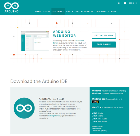
De software
Voorbereiding IDE
- Download de Arduino IDE van:
https://www.arduino.cc/en/Main/Software
De software maakt gebruik van libraries. Dit is software door anderen geschreven
welke functies bevat waar je anders maanden mee bezig was om uit te zoeken en te
programmeren. Nu kan je dat werk dat anderen voor je uitgezocht hebben gebruiken.
De Arduino-programmeeromgeving biedt een groot scala aan libraries aan.
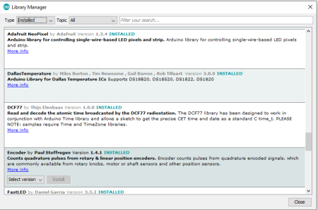
Om deze Fibonaccikloksoftware te kunnen aanpassen moet in de Arduino IDE de
volgende libraries geinstalleerd worden:
dit gaat als volgt:
- In het IDE-menu open: Sketch->Include library -> manage libraries
- Zoek de volgende libraries en installeer ze
Adafruit Neopixel
Encoder by Paul Stofregen
Keypad by Mark Stanley, Alexander Brevig
RTClib bij Adafruit
Wat ook kan is alle libraries van deze
ZIP-file kopieren naar de folder waar de sketches staan.
In deze sketchfolder bevindt zich een folder "libraries". Kopieer de inhoud van
de ZIP-file hierin.
Er zijn veel soorten Arduino's. wij gebruiken de Arduino Nano
In het menu: Tools -> board kan je de Arduino Nano selecteren
Kies bij Processor ATMEGA328p (Old bootloader)
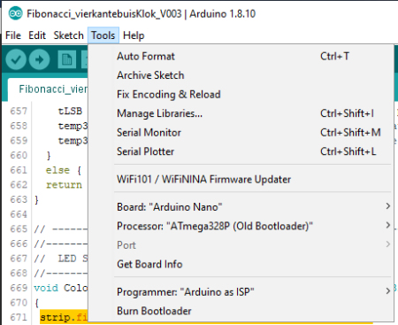
Om de code in de Arduino Nano te plaatsen moet een Arduino via een de USB-kabel
aan de PC worden aangesloten.
Port wordt dan zwart en er kan een compoort worden aangevinkt
Als daarna de pijl naar rechts onder edit in het menu wordt gedrukt wordt het
programma in de Arduino nano geladen.
Het programma en zijn algoritmen
Met #define kunnen de gebruikte onderdelen geselecteerd worden worden.
Door twee slashes // voor een #define te zetten wordt de optie uitgeschakeld.
In het programma zijn de stukken die coderen voor een onderdeel te herkennen aan de
programmaregels tussen #ifdef en #endif.
Het stukje code wordt
niet gecompileerd in de software als het niet met een #define gedefinieerd is.
                     #ifdef ROTARYMOD
#include <Encoder.h>             // For rotary encoder
                    #endif ROTARYMOD
De software ondersteunt WS2812 of SK6812 LED-strips.
Kies een van deze.
Daarnaast kan er gekozen worden tussen een draaiknop (ROTARYMOD) of een keypad
(KEYPAD).
De klok kan zonder DS3231-tijdmodule werken. Het werkt dan met de klok van de
processor.
Deze processorklok heeft een afwijking van seconden per dag. Dit is alleen
handig om de software te testen.
Een DS3231-module heeft een afwijking van slechts een minuut per jaar.
Als #define MOD_DS3231 is uitgezet wordt de processorklok gebruikt.
//--------------------------------------------
// ARDUINO Definition of installed modules
//--------------------------------------------
//#define LED2812            // Use  RGB LED strip WS2812
#define LED6812            // Use RGBW LED strip SK6812
#define ROTARYMOD          // Use rotary encoder
//#define KEYPAD             // Use a 3x4 keypad
#define MOD_DS3231         // DS3231 RTC module installed
//--------------------------------------------
// ARDUINO Includes defines and initialisations
//--------------------------------------------
                     #ifdef ROTARYMOD
#include <Encoder.h>             // For rotary encoder
                     #endif ROTARYMOD
#include <Wire.h>                // Communication with
#include <RTClib.h>              // For RTC module
#include <EEPROM.h>              // To store data in EEPROM
#include <TimeLib.h>             // For time management
#include <Adafruit_NeoPixel.h>   // for LED strip WS2812 or SK6812

                     #ifdef KEYPAD
#include <Keypad.h>               // For 3x4 keypad
                     #endif KEYPAD
Bij "Pin Assigments" wordt een leesbare naam voor een pin gedefinieerd.
Digitale pinnen kunnen alleen aan of uit worden gezet of worden uitgelezen.
Bij analoge pinnen kunnen voltages tussen 0 en 5 V worden gemeten of aangestuurd
worden
met waarden tussen 0 en 1024 .
//--------------------------------------------
// PIN Assigments
//--------------------------------------------

enum DigitalPinAssignments {
 EncoderPow   = 2,                // give power to Encoder
 clearButton  = 3,                // switch (labeled SW on decoder)
 encoderPinA  = 4,                // right (labeled DT on decoder)
 encoderPinB  = 5,                // left (labeled CLK on decoder)
 EmptyD06     = 6,                // EmptyD06
 EmptyD07     = 7,                // EmptyD07
 EmptyD08     = 8,                // EmptyD08
 EmptyD09     = 9,                // EmptyD09
 EmptyD10     = 10,               // EmptyD10                                 SS
 LED_PIN      = 11,               // Pin to control colour SK6812 WS2812 LEDs MOSI
 EmptyD12     = 12,               // EmptyD12                                 MISO
 secondsPin   = 10};              // if set to 13 led will blink on board     SCK
                                  // Analogue hardware constants ----
enum AnaloguePinAssignments {
 PhotoCellPin  = 2,               // LDR pin
 EmptyA3       = 3,               // EmptyA3
 SDA_pin       = 4,               // SDA pin
 SCL_pin       = 5};              // SCL pin
Na deze "Pin Assigments" volgen in de software nog meerdere definities van variabelen.
De Arduino gaat na de initialisaties de functie setup() uitvoeren.
Hierin worden allerlei functies van de libraries aangezet en de analoge en
digitale pinnen gedefineerd voor in- of uitvoer.
Na de setup() wordt de functie loop() zoals de naam doet vermoeden eindeloos van
begin tot eind in een lus doorlopen.
Dit is het hart van de
coding waar vanuit alles wordt aangestuurd en berekend.
//--------------------------------------------
// ARDUINO Loop
//--------------------------------------------
void loop(void)
{
 SerialCheck();
 if(Demo)  Demomode();
 else
  {
   EverySecondCheck();
   if(!KeyInputactivated) EveryMinuteUpdate();                      // if keyboard input then do not update display
                              #ifdef ROTARYMOD
   RotaryEncoderCheck();
                              #endif ROTARYMOD
  }
}
//--------------------------------------------
// ARDUINO Setup initialise the hardware
//--------------------------------------------
void setup()         // initialise the hardware // initialize the appropriate pins as outputs:
{
 Serial.begin(9600);                                               // setup the serial port to 9600 baud

 pinMode(secondsPin,   OUTPUT );
                          #ifdef ROTARYMOD
 pinMode(encoderPinA,  INPUT_PULLUP);
 pinMode(encoderPinB,  INPUT_PULLUP);
 pinMode(clearButton,  INPUT_PULLUP);
 pinMode(EncoderPow,   OUTPUT );
 digitalWrite(EncoderPow,HIGH);                                     // Provide the rotary encoder with power
 Tekstprintln("Rotary encoder enabled");
                          #endif ROTARYMOD

 strip.begin();                                                     // Start communication to LED strip
 strip.setBrightness(BRIGHTNESS);                                   // Set brightness of LEDs
 ShowLeds();
et cetera ......
De software kijkt razendsnel in de loop of er wat serieel wordt ingetikt, of de
demo stand is aangezet en of er aan de draaiknop wordt gezeten.
Verder zijn er nog eens per seconde en eens per minuut acties die de overige
aandacht van de software eist.
Elke seconde wordt de lichtintensiteit van de LDR uitgelezen. Deze intensiteit
wordt gewogen met de vorige uitlezing zodat de lichtsterkte van de LEDs gedempt
aangepast wordt.
Van de uitlezing van de LDR, die tussen 0 en 1024 ligt, wordt de wortel genomen
zodat de lichtsterkte parabolisch wordt aangepast.
De klok verandert elke minuut de tijdsweergave. Elke minuut de worden de
getallen 1,1,2,3,5 random een keer gekozen uit een array gekozen en opgeteld.
Als de waarde overeenkomt met de gewenste waarde dat worden deze getallen naar
de klok gestuurd. Een processor is zo enorm snel dat deze methode eleganter
werkt dan alle mogelijkheden in een lijst te stoppen. Zeker als geheugenruimte
beperkend is.
De kleurenpalettes zijn in een array colors[][] vastgelegd.
Bijvoorbeeld pallette nummer 1:
{ white, red , yellow, blue }, //#1 Mondriaan
Als een compartiment leeg moet blijven, de waarde nul heeft, wordt de kleur wit.
Is er een kleur voor een uur dan wordt hij rood. Als de minuut gekleurd moet
worden dan wordt de kleur geel. Als het compartiment zowel rood als geel is
wordt de kleur blauw.
De variable bits[] houdt dit bij. Het kan de waarde 0, 1, 2 of drie hebben.
Bediening
De klok wordt met de rotary bediend.
De rotary kan gedrukt en gedraaid worden.
Door te drukken op de knop wordt de knop geactiveerd. Na 60 seconden wordt deze
weer gedeactiveerd.
Een keer drukken geeft de mogelijkheid de uren te veranderen. De display wordt
dan even rood. Door aan de knop te draaien worden de uren vooruit of achteruit
gezet
Een tweede druk binnen 60 seconden doet display geel kleuren waarna de minuten
aangepast kunnen worden.
Een derde druk geeft de mogelijkheid de maximale helderheid aan te passen.
Daarna kunnen de diverse kleurplattes geselecteerd worden.
De instellingen worden bewaard als de stroom van de klok wordt gehaald.
Om de klok te resetten moet 20 keer of meer gedrukt worden of lang ingedrukt
houden.
switch (NoofRotaryPressed) // No of times the rotary is pressed
{
case 1: ChangeTime = true; ColorLeds("",0,NUM_LEDS-1,0XFF0000); ShowLeds(); delay(1000); break; // Change the hours RED
case 2: ChangeTime = true; ColorLeds("",0,NUM_LEDS-1,0XFFFF00); ShowLeds(); delay(1000); break; // Change the minutes YELLOW
case 3: ChangeLightIntensity = true; ColorLeds("",0,NUM_LEDS-1,0XFFFFFF); ShowLeds(); delay(1000); break; // Change intensity
case 4: DisplayPalette = 1; break;
case 5: DisplayPalette = 2; break;
case 6: DisplayPalette = 3; break;
case 7: DisplayPalette = 4; break;
case 8: DisplayPalette = 5; break;
case 9: DisplayPalette = 6; break;
case 10: DisplayPalette = 7; break;
case 11: DisplayPalette = 8; break;
case 12: DisplayPalette = 9; break;
case 13: DisplayPalette = 0; break;
case 14 ... 19: break;
default: NoofRotaryPressed = 0; Reset(); break;
}
Keypad
The 3x4 key keypad in the current software is too large to stick on the clock, but can be used for a cabinet.
Serial control
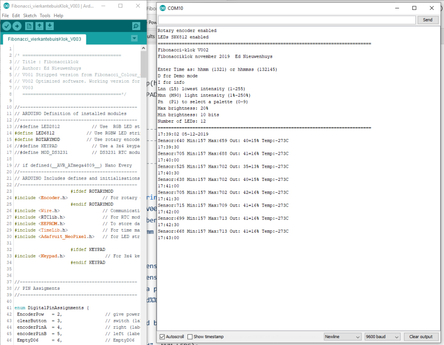
After the clock is connected to the PC with a serial cable, the clock can be controlled with the Arduino-IDE software.
Entering 'i' brings up a menu in the "serial monitor" of the Arduino IDE.
The time and the measured light intensity are printed every thirty seconds.
With a connected DS3231 time module, the measured temperature +/-5C is also shown.
Sensor:683 Min:157 Max:736 Out: 41=16% Temp:22C
Sensor: is the current measurement between 0 and 1024 bits.
Min: is the lowest measured bits and Max: the highest.
Out: is the calculated light intensity (0-255). In this case 16%.
The menu after pressing I is as follows:
Enter Time as: hhmm (1321) or hhmmss (132145)
D for Demo mode
I for info
Lnn (L5) lowest intensity (1-255)
Mnn (M90) light intensity (1% -250%)
Pn (P1) to select a palette (0-9)
Max brightness: 20%
Min brightness: 10 bits
Number of LEDs: 12
The lowest light intensity sent to the clock can be set with L.
The clock will then not turn on softer than that value when it is completely dark.
L5 is a nice value.
The maximum strength can be set with M. Sometimes the clock is too bright or too dim for the place where it is located.
M80 is the default value.
The color palette can be selected with P. P1 is standard.
With D the clock goes into demo mode until D is entered again or the clock is turned off.
Good luck
Ed
Attachments
Arduinostoksoftware V002 als ZIP-file
Arduinostoksoftware V005 als ZIP-file
Arduino stick software V023 as ZIP file This version contains software for the 3-button membrane
11 sept 2023, 31 jan 2020, 15 dec 2019
Mail: Ed Nieuwenhuys
www.arach.nl