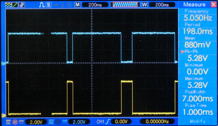
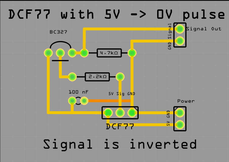
To get this inversed (yellow) signal a inverter was made with a PNP-transistor BC327.
The 4.7K resistor is for pulling down the signal.
The 2.2K resistor is for safety. With out the resistor the circuit also operates.
The 100 nF ceramic capacitor is added for a smoother signal.
A BC556 transistor also works well.
But as I found out later the software
has an option to use inverted signals.
The library initialization contains a third
parameter; OnRisingFlank.
This is default set to true (HIGH).
Initialize the library as follows:
DCF77 DCF = DCF77(DCF_PIN,DCF_INTERRUPT, LOW);
|
 |
Below are the functions the library gives you to use:
//Initialize library
DCF77(DCF77Pin,DCFinterrupt,OnRisingFlank);
time_t getTime(); // Returns the current time in CET
time_t getUTCTime(); // Returns the current time in UTC
Start(); // Start listening to DCF77 signal
Stop(); // Stop listening to DCF77 signal
|
Nice links with info about DCF receivers:
Online signal from Mainflingen on website
Explains the bits in the received string Arduino projects 4you
HKW-Elektronik GmbH Sells all kinds of receivers
Rheinturmfunkuhr mit Arduino
Arduino DCF77 radio clock receiver ,Matthias Dalheimer
Github Thijs Elenbaas
Conrad receiver
|
To use the ATTINY85 program
must be uploaded with a Clock speed of16MHz processor.
The signal wire must be must be attached to Pin3 and the interrupt must be
set to 0 in the program algorithm.
Detecting Rising flank interrupt 0 seems only be possible on pin3 was a suggestion in a forum.
A processor running at 16MHZ seems essential without changing the library timings.
Because the ATTINY85 does not have a serial.print I used the heartbeat subroutine to indicated that a time has been received.
Until the program received a proper decoded date/time it shows the DCF77 signal that is received.
The signal should be steady, turning on and off every second.
If not turn de rod and keep it horizontal. Step back a meter and let it start receiving.
Keep in mind nearby processors, magnetrons and bad power supplies disturbs the received signal.
A bad power supply set me back for weeks. Even a bad power supply in the
same power supply socket disturbs a signal.
The INO source file
|
 |
// Version 04. Ed Nieuwenhuys 7 may 2017
// ATtiny45 / ATtiny85
//
// |----U----|
// Pin 5 Reset | 1 o 8 | VCC
// (Analog input 3) Pin 3 | 2 7 | Pin 2 (Analog Input 1, SCK)
// (Analog input 2) Pin 4 | 3 6 | Pin 1 (PWM, MISO)
// -GND | 4 5 | Pin 0 (PWM, AREF, MOSI)
// |---------|
//
#include "DCF77.h"
#include "TimeLib.h"
enum PinAssignments
{
PIN01 = 0,
DCF_LEDP1 = 1,
DCF LedPin PIN02 = 2,
DCF_PIN = 3, // DCF Pulse on interrupt pin
PIN04 = 4,
PIN05 = 5,
};
static unsigned long msTick; // the number of millisecond ticks since we last incremented the second counter
//-------------------------------------------- // Heartbeat //--------------------------------------------
uint8_t hbval = 128;
int8_t hbdelta = 8;
static unsigned long last_time = 0;
time_t time;
byte Heartbeat = 0;
//--------------------------------------------
// DCF-2 DCF77 MODULE
//--------------------------------------------
#define DCF_INTERRUPT 0 // Interrupt number associated with pin
byte DCF_signal = 0; // is a proper time received?
DCF77 DCF = DCF77(DCF_PIN,DCF_INTERRUPT,LOW);
void setup()
{
DCF.Start();
pinMode(DCF_LEDP1, OUTPUT );
pinMode(DCF_PIN, INPUT_PULLUP);
analogWrite(DCF_LEDP1, 5);
msTick = millis();
}
void loop()
{
time_t DCFtime = DCF.getTime(); // Check if new DCF77 time is available
if (DCFtime!=0)
{
setTime(DCFtime);
Heartbeat = 1;
}
if (Heartbeat) heartbeat();
else digitalWrite(DCF_LEDP1,1-digitalRead(DCF_PIN)); //Turn on/off the led
}
void heartbeat()
{
unsigned long now = millis();
if ((now - last_time) < 40) return;
last_time = now;
if (hbval > 230 || hbval < 20 ) hbdelta = -hbdelta;
hbval += hbdelta;
analogWrite(DCF_LEDP1, hbval);
}
|