The Fibonacci clock was a kick starter project of
Philippe Chrétien.
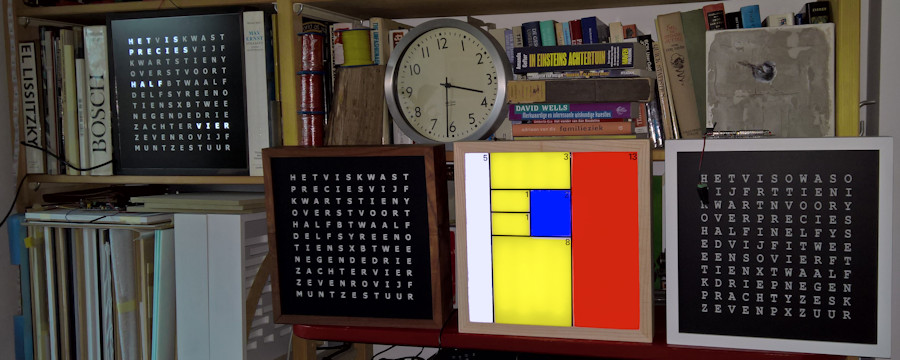
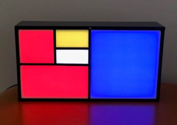
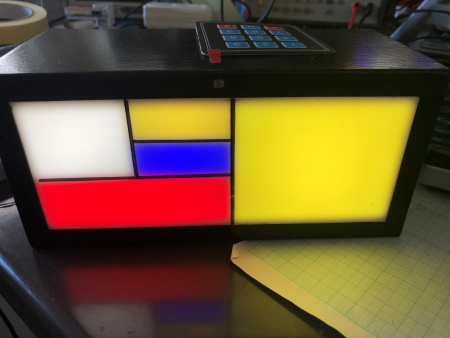
What make this idea so beautiful is it simplicity, its ingenuity and the ever
changing Mondriaan look alike display. Mondriaan searched and reached his
ultimate simplicity in his paintings from realism to cubism and finding
presenting his portraits and landscapes in primary colours and rectangles.
But a clock? Fibonacci?
 |
 |
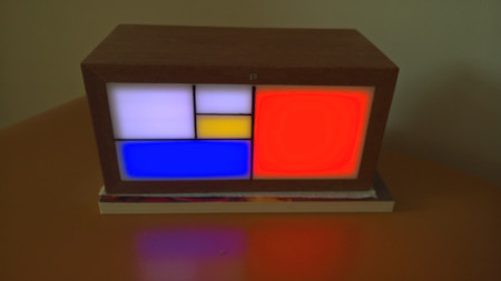
Red+Blue = hour, (Yellow+Blue)*5 = minutes. 5 + 3 = 8 hours, 1 + 3 = 4, 4 x 5 = 20 minutes |
That's all that is inside. |
 |
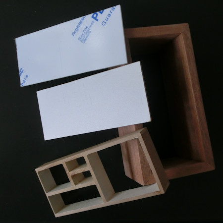 |
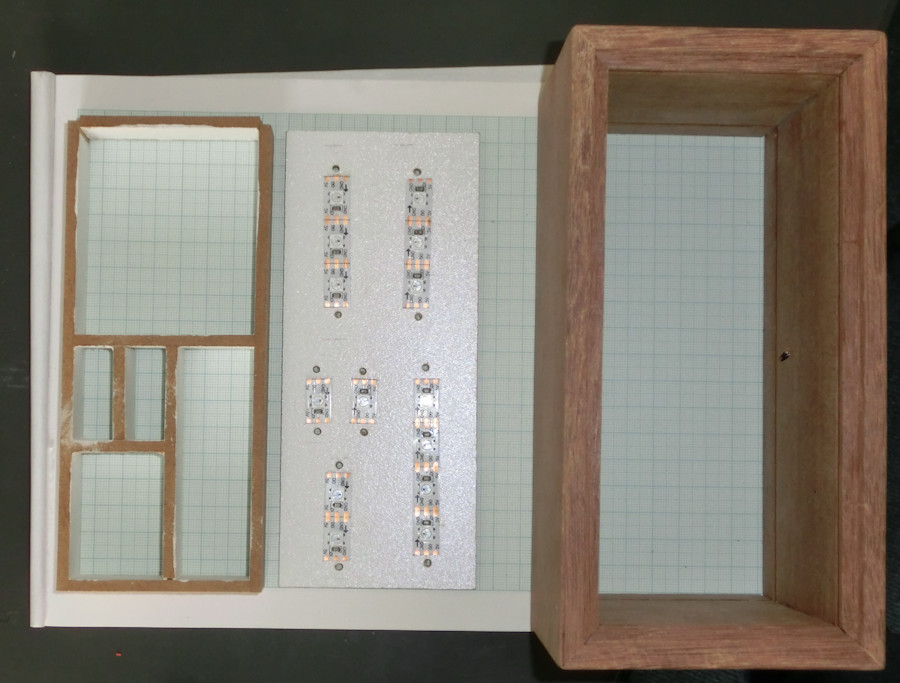
| The casing building blocks |
First make the case. In this example a case of 10 x 10 x 20 cm.
Then the light compartments
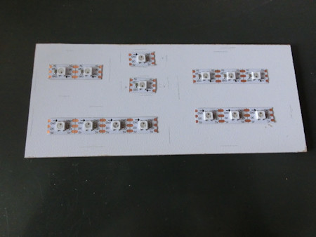
and the ground plate on which the colour LEDs are
glued.
The inside of the compartments should be pure white to avoid colour bleeding in the
display.
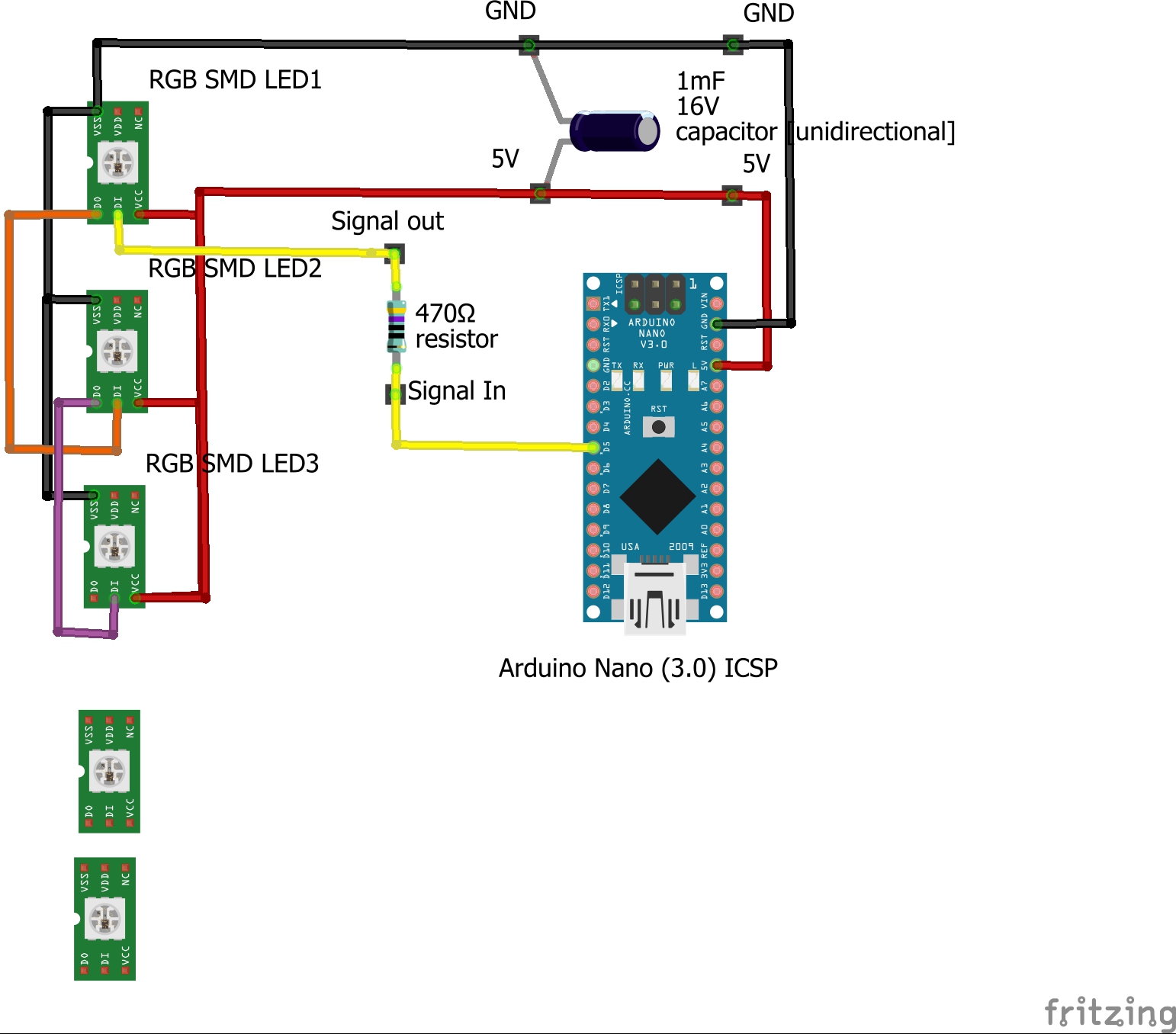
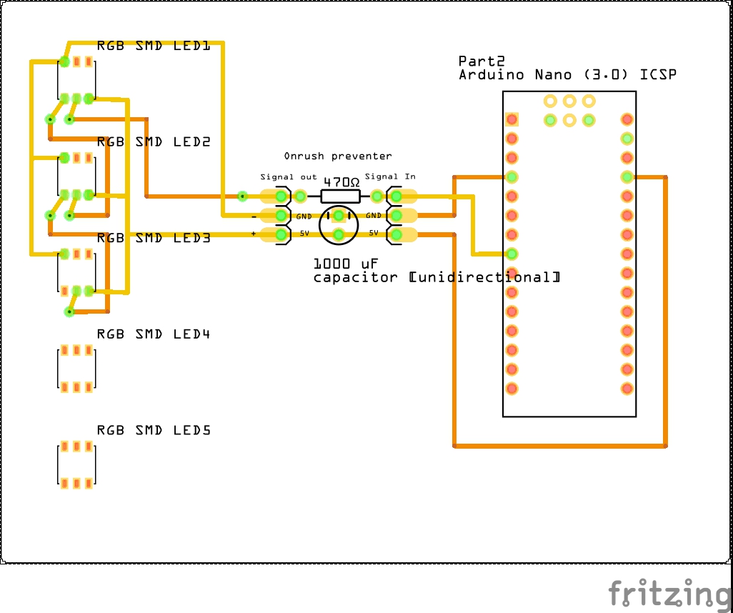
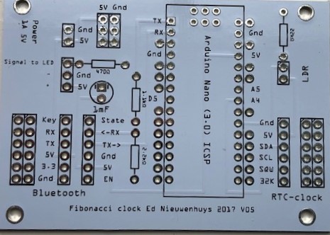
You can use this Fritzing design but the clock can easily be made without it
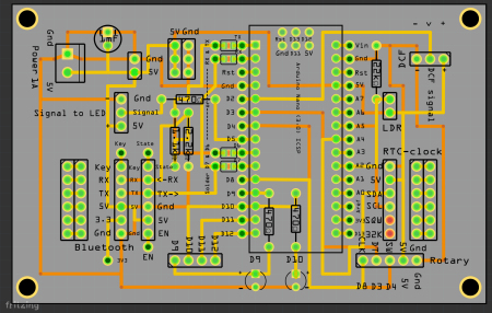
| Arduino Nano | ||
| PCB for Fibonnacci-klok Fritzing PCB V014 |
 |
|
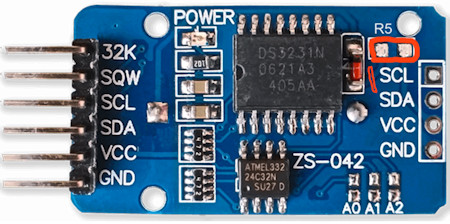
| 1 x RCT DS3231 Precision clock module ZS-042 |
|
|
| 1 x CR 2032 3V lithium battery |  |
|
| 1 x Dupont-kabel F-F, 20-wires |
|
|
| 2 x 6-pin female socket connector |  |
|
| 1 x KY-040 Keyes Rotary Encoder |  |
|
| 1 x light sensor | |
|
| 1 x 22kΩ resistor | |
|
| 1 x 1000 µF capacitor | |
|
| 1 x 470Ω + 1.1kΩ + 2.2kΩ resistor | 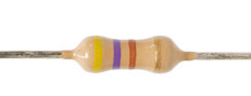 |
|
| 1 x Power supply 5V DC 2 Ampere |
|
|
| 1 x 50 cm black-red power wire (0.14 mm2) |
|
|
| 1 x set schrink tube 20 cm x 1.5 mm diam + 10 cm x 5 mm diam | |
|
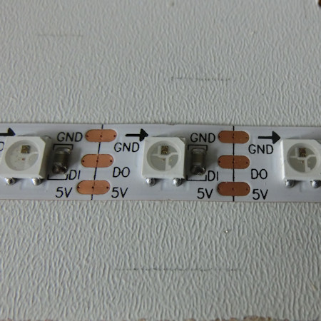
| 12 LEDs WS2812B or SK6812 | |
|
| Optional | ||
| Wireless Serial 6 Pin Bluetooth RF Transceiver Module HC05 (Android, W10 | ||
| Wireless Serial 6 Pin Bluetooth RF Transceiver Module HM10 (voor Iphone, IPad) | ||
| DCF77 DCF-2 module | 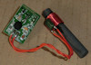 |
Soldering the parts
Always check the resistors with a multimeter before
soldering them.
The Arduino Nano is not soldered to the PCB. Use the 15-pin sockets. It is then
still possible to replace the Arduino if it becomes defective
To solder the feet parallel, it is useful to insert the Arduino loosely (do not
press it all the way in) and solder the corner points first.
The longest leg of the capacitor is the +, positive terminal.
The - also indicated by the white vertical line is often printed with a - on the
capacitor.
The longest leg of the LED is the +, positive pole.
The minus of the LED is connected to the triangular piece of metal in the LED.
The light-sensitive sensor (LDR) has no polarity.
Preferably mount the LDR in the edge of the cabinet.
In my clocks I drill a hole slightly diagonally horizontally through the top
shelf.
The 1.1 and 2.2 kohm resistors are needed when a Bluetooth module is connected.
The resistance values are indicated on the PCB.
The clock with up to 15 LEDs can be powered with the USB cable that goes into
the Arduino.
It is also possible to connect 5V in various places on the PCB, which then also
feeds the Arduino.
Cut an old USB cable and use an old telephone plug-in power supply as a power
source.
The clock draw a maximal current of 0.15A at 5V.
The RTC time module contains a LIR2032 or CR2032
battery.
The LIR2032 is a rechargeable CR2032. If there is a CR2032 in the RTC time
module, it is advisable to remove the small resistor above the text SCL on the
back of the module.
This resistor can be desoldered with a soldering iron.
Rotary knob
If a rotary knob is connected, connect:
D3 to DT on decoder,
D4 to SW on decoder,
D8 to CLK on decoder
and connect the + to 5V and GND to GND.
The clock can be operated with the rotary by pressing the button.
Pressing the button activates the menu.
After 60 seconds you must press again.
This prevents interference pulses from the mains from changing the time.
Once you press the button, the hours can be adjusted by turning the knob. Two
pushes the minutes.
Press three times to increase the brightness. Pressing four times or more gives
a choice between the various color palettes.
Default is the Mondrian color palette.
It is quite difficult to set the time with the rotary dial.
The membrane buttons or a Bluetooth connection with a mobile phone app are
recommended.
4x3 membrane keypad
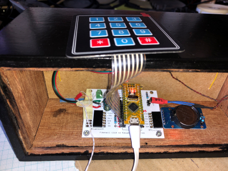
If a 4x3 keypad is used the 7 connection can be connected to pin 6 - 12 on the
Nano.
If you look at the top of the keypad the wire below #
is connected to pin6.
Bluetooth met de HM10 BLE voor Apple IOS en Android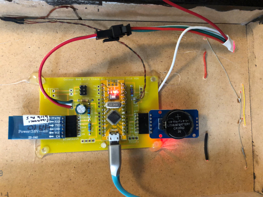
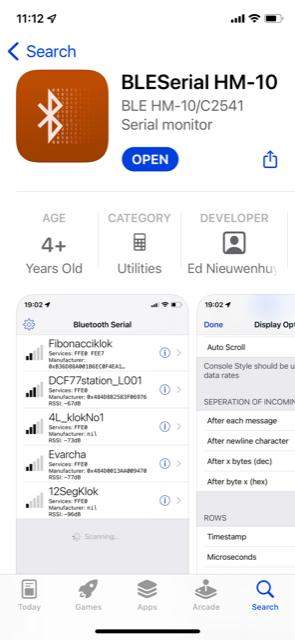
With a HM10 BLE module the clock can communicate with Apple IOS and Android.
Install on your iPhone the app
"BLEserial
HM-10", "BLESerial
Pro" or the free "BLEserial tiny" (App store).
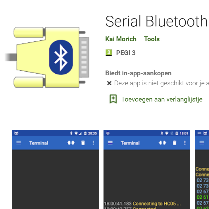
Serial Bluetooth Terminal
from Kai Morich works
fine as terminal on Android.
Connect with "Serial Bluetooth Terminal" to start communication.
After connection with the clock time and light intensity is transmitted
every 30 seconds.
With the commando: I of i a menu with possible commands is transmitted
and displayed in the terminal of the app.
More info about Bluetooth here
Software
The last stable version. Source code V038
Older simple version Source code V007
All on Github
Used libraries
#include <Encoder.h>             // http://www.pjrc.com/teensy/td_libs_Encoder.html
#include <Wire.h>                // Default Arduino library
#include <RTClib.h>              // https://github.com/adafruit/RTClib
#include <EEPROM.h>              // Default Arduino library To store data in EEPROM
#include <TimeLib.h>             // Arduino library Time by Michael Margolis   http://playground.arduino.cc/Code/Time/
#include <Adafruit_NeoPixel.h>   // https://github.com/adafruit/Adafruit_NeoPixel   for LED strip WS2812 or SK6812
#include <"Adafruit_Keypad.h">   // https://github.com/adafruit/Adafruit_Keypad//
#include <SoftwareSerial.h>      // Arduino library for HC12 or Bluetooth
FibonacciKlok_V007 (Als zip file)
Oudere versies
Fibonacci Versie 16. (As ZIP-file) This version works with the Arduino Nano and a Bluetooth module.
With the #defines options in the source code, like a DCF77 receiver, can be turned on or off
If link is broken the library from my place
Ed Nieuwenhuys,
26 november 2023